
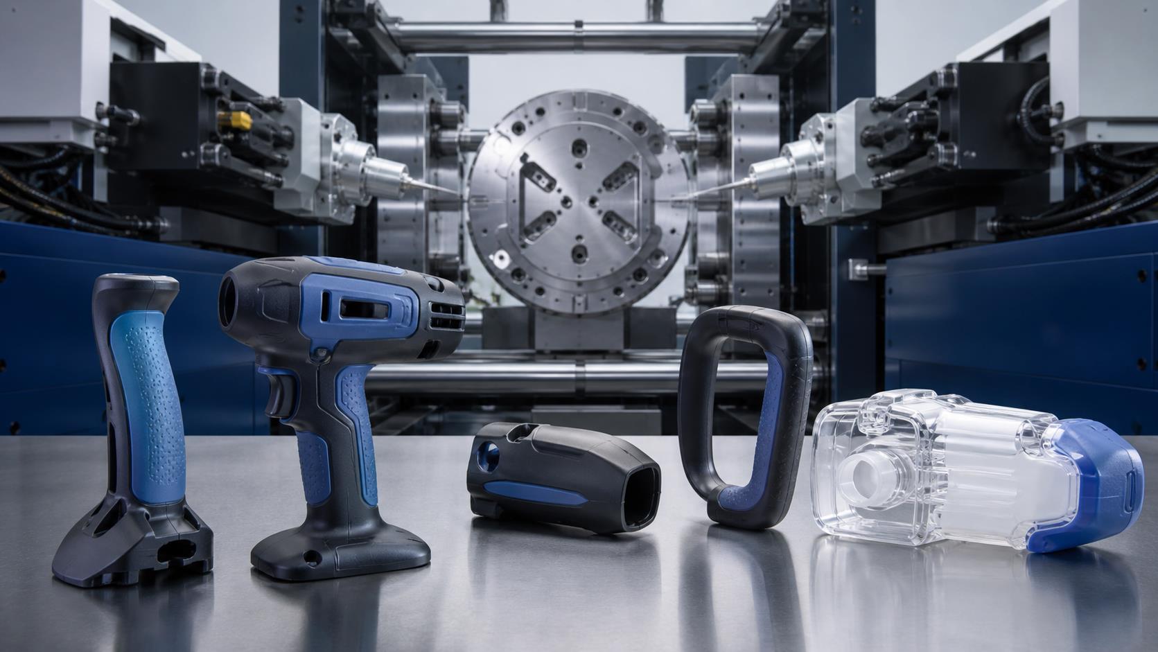
Two-shot injection molding, also called 2K injection molding, two-color injection molding or two-component molding, combines two colors or materials in one finished plastic component. It supports rigid-and-soft grips, transparent-and-opaque housings, integrated seals and other multi-material molding functions.
Compared with conventional molding, two-shot mold design requires tighter coordination between product geometry, material sequence, mold rotation, machine configuration, gating, cooling, ejection, adhesion, shrinkage and dimensional tolerances. The following 36 practical guidelines help reduce flash, deformation, bonding problems, misalignment and expensive mold-trial changes.
1. Material and Two-Shot Molding Sequence
1.1Choose the Basic Sequence
As a starting rule, mold hard plastic before soft plastic, transparent material before opaque material and the higher processing-temperature material before the lower-temperature material.
1.2Hard Material First
In most rigid-and-soft applications, the rigid substrate is molded first because soft materials are more easily deformed during handling and second-shot filling.
1.3ABS, PC and PMMA Sequence
For combinations such as ABS with PC, PC plus ABS or PMMA, mold the higher-temperature PC, PC blend or PMMA component first when validated for the selected grades.
2. Rotation, Guide Systems and Symmetry
2.1Symmetrical Guide Pins and Bushings
Arrange guide elements symmetrically in both axes so the front and rear mold realign correctly after rotation.
2.2Design for 180 Degrees
Check alignment, cooling, ejection, layout, guide systems and machine clearance in both rotary positions.
2.3Symmetrical Side Locks
Position side locks around the mold center so they match in both orientations.
2.4Verify the Rotated Assembly
Rotate the complete design digitally around its true center and confirm that every relevant mold component still aligns and functions.
3. Match the Two-Shot Mold to the Machine
3.1Match Nozzle Spacing
The distance between molding positions must correspond to the actual injection-unit spacing, whether adjustable or fixed.
3.2Confirm Nozzle Direction
Verify whether parallel injection units are arranged along the machine X-axis or Y-axis before laying out cavities.
3.3Check Mold Thickness
Confirm minimum and maximum mold thickness, platen dimensions, ejector spacing and installation limits. The source example uses at least 170 mm for the front panel plus A plate, but actual machine data governs.
3.4Control Sprue Position
The example guideline limits front sprue depth to 65 mm and calls for at least 150 mm from the upper sprue top to the mold-base center. Verify against the selected machine and structure.
4. Ejection, Cooling Connections and Mold Location
4.1Independent Ejection Systems
Use two ejection systems with layouts that correspond through rotation rather than simple translation.
4.2Spring Return
Use an ejector-plate return method that cannot interfere with rear-mold rotation; spring return is commonly preferred.
4.3Ejector-Rod Hole Design
Slotted holes may be required when machine ejector spacing and mold position do not correspond. Confirm the real machine configuration.
4.4Rotary Cooling Connections
Keep each circuit inlet and outlet on appropriate fixed sides and make sure hoses remain connectable after 180-degree rotation.
4.5First-Shot Position
Position the first shot on the non-operator side when practical, transferring the final part to the operator side after rotation.
4.6Clamping Locations
For automated or export molds, place clamping provisions where they do not interfere with machine installation or automation.
5. Parting Surfaces, Datums and Critical Tolerances
5.1Define Parting Surfaces Correctly
Base the rear-mold parting surface on the combined two-stage geometry, while front-mold parting surfaces normally follow each individual shot.
5.2Use the Guide Center as Datum
When machining remaining sprue and ejector holes, reference the center established by the four symmetrical guide holes to avoid rotational mismatch.
5.3Improve Front-Rear Positioning
Use sufficient taper or height difference at contact and shutoff surfaces. The source suggests more than 0.1 mm where applicable.
5.4Control Mold Tolerances
Tight position and depth tolerances are required so height or alignment errors do not create flash after rotation.
| Source design reference | Recommended value | Purpose |
|---|---|---|
| Front and rear flange tolerance | Minus 0.05 mm | Control machine and mold interface |
| Distance between flanges | Plus or minus 0.02 mm | Maintain rotary positional relationship |
| Ejector rod to hole clearance | 0.1 mm per side | Allow reliable ejector movement |
| Guide-pin and bushing center distance | Plus or minus 0.01 mm | Preserve alignment after rotation |
| Mold-frame depth tolerance | Minus 0.02 mm | Reduce height mismatch and flash |
Reference only: These values reflect the source design experience and are not universal standards. Final tolerances must follow the mold architecture, machine, component size, material and validated manufacturing process.
6. Rotary and Non-Rotary Two-Shot Mold Structures
6.1Rear-Mold Rotation
The rigid first shot remains on the core while the rear mold rotates to the soft-material position. Runner separation, retention, ejection and shrinkage must be designed together.
6.2No-Rotation Configuration
A second injection unit positioned about 90 degrees can mold through slides or shutoffs without rotating the mold in selected applications.
6.3Cavity-Core Relationship
In the described rotary layout, the two cavities differ because each creates one stage, while the corresponding core profiles remain identical.
6.4Two Locating Rings
Provide the locating-ring arrangement required by the selected rotary machine and rear-mold bottom plate.
6.5Ejector-Rod Positions
The source uses about 210 mm minimum spacing and extended rods projecting about 150 mm for certain large molds. Confirm all dimensions with the actual machine.
6.6Rotary Mold Accuracy
Both rotary stations must maintain consistent dimensions, alignment and fit. A hydraulic ejector on the rotary table may be needed when standard ejection cannot operate.
7. Protect and Seal the First-Shot Component
7.1Protect the First Shot
Provide controlled local clearance so the second cavity does not scrape or crush the first-shot plastic, while retaining strong sealing areas.
7.2Use Controlled Compression
A slightly larger first-shot feature can be compressed at the second station to improve sealing when deformation and stress remain acceptable.
7.3Control Slider Timing
If a slider or lifter could strike the retained product, close the A and B plates first and return the moving feature afterward.
7.4Control Second-Shot Impact
Review gate location, flow direction, local support, shutoff geometry and injection settings so incoming melt does not move or deform the substrate.
8. Cooling, Gating and Two-Shot Mold Accuracy
8.1Balance Cooling
Make cavity and core circuits complete, balanced and consistent to stabilize temperature, dimensions and cycle time across both shots.
8.2Select Gates Carefully
A submarine gate can automatically separate the first-shot runner. Three-plate and hot-runner systems are alternatives when geometry requires them.
8.3Consider Both Shrinkages
The first-shot material often controls overall geometry, but evaluate shrinkage, flowability, structure and compatibility as one two-material system.
9. Material Compatibility and Adhesion
9.1Select Compatible Materials
Evaluate interfacial adhesion, shrinkage difference, processing temperature, flow behavior, thickness and service environment. Common systems include rigid ABS or PC with soft TPE.
Improve the Bonding Interface
Texture selected bonding regions
Add mechanical interlocks
Use sealing grooves
Provide suitable material thickness
Validate mold-surface finish and process temperature
| Two-shot combination | Main design concern | Validation focus |
|---|---|---|
| Same resin, different colors | Color boundary and contamination | Purging, gate balance and appearance |
| Rigid plastic plus TPE | Chemical adhesion and substrate deformation | Peel strength, shutoff, temperature and mechanical lock |
| Transparent plus opaque plastic | Interface appearance and optical defects | Material sequence, sealing, stress and visibility |
| Full soft overwrap | Retention and overall shrinkage | First-shot geometry, support and interface bonding |
| Contour-to-contour interface | Flash, gaps and differential shrinkage | Both material shrinkages and precision shutoff |
10. Large Transparent Two-Shot Part Design
10.1Seven Additional Design Controls
Confirm the gate early: reserve its position during product development with the mold manufacturer.
Control thickness: the source suggests at least 0.8 mm transparent material and 0.7 mm opaque material where applicable.
Optimize openings: keep widths around parting surfaces and holes consistent, using about 0.5 mm as the source reference where suitable.
Control opaque ribs: about 0.5 to 0.6 mm is the source guideline to reduce sink marks in thin opaque regions.
Be cautious with large optical lenses: integrated primary optics require advanced tooling, equipment and process validation.
Perform reliability tests: include drop testing and thermal shock; the source example uses minus 40 degrees C to 65 degrees C for 48 hours.
Simplify the structure: move complex features to mating parts where possible and protect the material interface.
11. Key Two-Shot Injection Mold Design Checklist
Define the correct first-shot and second-shot material sequence.
Design around the actual 2K injection molding machine.
Verify alignment after 180-degree rotation.
Keep guide, core, cavity and mold-base structures appropriately symmetrical.
Use independent and reliable ejection systems.
Design balanced cooling circuits in both rotary positions.
Select gates and flow directions to protect the first-shot part.
Provide strong shutoff surfaces to prevent flash.
Validate material adhesion, compatibility and shrinkage.
Check sliders, lifters and return timing through the full sequence.
Control transparent and optical areas with additional care.
Confirm nozzle spacing, mold thickness, platen and ejector interfaces before manufacture.
Two-Shot Injection Molding FAQ
What is the difference between two-shot molding and overmolding?
Two-shot molding normally uses two injection units and transfers the first shot to a second molding position within an automated cycle. Overmolding is a broader term and may also describe molding a second material over a separately produced insert or substrate.
Which material should be molded first in 2K injection molding?
Common starting rules are hard before soft, transparent before opaque and higher processing-temperature material before lower-temperature material. Final sequence depends on geometry, adhesion, flow and material data.
Why is 180-degree rotation verification important?
The rear mold, guides, cooling, ejection and retained component must align and operate in both positions. A small asymmetry can cause interference, flash or mold damage.
How can bonding between two materials be improved?
Select chemically compatible grades, optimize processing temperature, provide sufficient contact area and add texture, sealing grooves or mechanical interlocking features where needed.
What commonly causes flash at the material interface?
Weak shutoff support, alignment error, incorrect first-shot dimensions, excessive second-shot pressure, substrate deformation and differential shrinkage can all contribute.
Need a Reliable Two-Shot Injection Molding Partner?
Zentoc supports product design review, two-shot mold manufacturing, material evaluation, mold trials and custom injection molding production.
Contact Zentoc