
Bearings support rotating shafts and moving parts while controlling friction, load and motion accuracy. They are generally divided into sliding bearings and rolling bearings, and may also be classified as radial, thrust or radial-thrust bearings according to load direction.
Correct bearing installation is essential for smooth rotation, dimensional accuracy, low friction and long equipment life. This guide explains sliding-bearing fitting, rolling-bearing mounting, clearance measurement and practical assembly precautions.
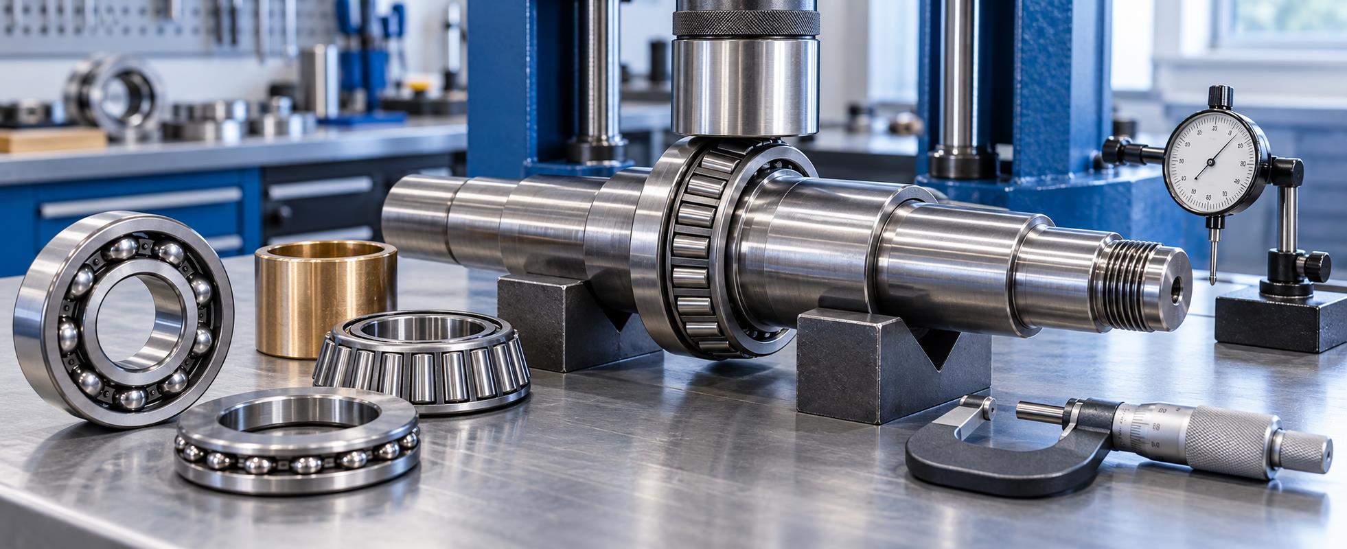 SEO topics: bearing installation, sliding bearing assembly, rolling bearing installation, bearing clearance adjustment, press-fit bearings, thermal fitting and tapered roller bearing preload.
1. Bearing Types and Load Directions
| Classification | Type | Main Characteristic |
|---|---|---|
| Friction principle | Sliding bearing | Shaft and bearing surfaces move with sliding friction and a lubricant film |
| Friction principle | Rolling bearing | Balls or rollers move between raceways to reduce friction |
| Load direction | Radial bearing | Primarily supports load perpendicular to the shaft axis |
| Load direction | Thrust bearing | Primarily supports load parallel to the shaft axis |
| Load direction | Radial-thrust bearing | Supports combined radial and axial loads |
2. Solid Sliding Bearings and Bushings
Solid sliding bearings, also called sleeve bearings or bushings, are simple bearing structures commonly produced from copper alloys or cast iron.
2.1 Installation Method
Light interference fits may use a wooden mallet or a hammer with a protective wooden block. Larger interference should use a mechanical press.
2.2 Alignment
Keep the bushing straight during insertion. Tilting can damage the bore, housing and fit.
2.3 Thermal Fitting
Controlled thermal assembly may be suitable in special applications when allowed by the design and material.
2.4 Lubrication Features
After installation, oil grooves and lubrication holes must align with the specified flow path.
2.5 Bore Correction
Correct deformation with reaming for smaller bores or scraping for larger bores where the process permits.
2.6 Anti-Rotation Location
Locating pins or joint screws may prevent the bushing from rotating in the housing.
3. Split Sliding Bearing Assembly
Split-journal bearings use upper and lower shells. They are convenient to inspect, adjust and disassemble, but correct housing contact and shell positioning are essential.
3.1 Housing Contact
Upper and lower shell backs must fit the housing bore. Thick-wall shells may be scraped using the housing as a reference.
3.2 Thin-Wall Shells
The source method considers about 0.1 mm projection of the shell parting surface above the housing parting surface sufficient; additional scraping is generally unnecessary.
3.3 Axial and Radial Location
Locating shoulders or pins prevent the shells from shifting in the housing.
3.4 Scraping Sequence
Fit the lower shell first, then install the upper shell and cap and refine both contact patterns as needed.
3.5 Shim Adjustment
Change shim thickness at the parting surfaces to adjust shaft clearance.
3.6 Final Acceptance
With the cap tightened, the shaft should rotate freely without excessive looseness and the contact pattern should meet requirements.
4. Measuring Sliding Bearing Clearance
The lead-wire method estimates clearance from the thickness of wire compressed between the shaft journal and bearing shell.
Place several lead wires with diameters greater than the expected clearance on the journal and parting surface.
Tighten the bearing cap so the shells are properly clamped.
Remove fasteners and carefully lift the bearing cap.
Remove the flattened wires without damaging them.
Measure each wire thickness with a micrometer.
Calculate the average thickness to estimate bearing clearance.
| Reference Item | Source Guidance |
|---|---|
| General clearance ratio | Approximately 1.5-2.5 per thousand of shaft diameter, expressed in millimeters |
| Example shaft diameter | 60 mm |
| Example calculated clearance | Approximately 0.09-0.15 mm |
5. Rolling Bearing Installation Requirements
Rolling bearings offer low friction, compact axial size, convenient replacement and relatively simple maintenance. Installation quality directly affects accuracy and service life.
5.1 Identification Face
Install the marked face where it remains visible when practical, simplifying later identification.
5.2 Shoulder Radius
The shaft or housing shoulder radius must be smaller than the corresponding bearing corner radius.
5.3 Alignment
The bearing must not be tilted on the shaft or inside the housing bore.
5.4 Thermal Expansion
Two-bearing arrangements must allow the shaft to expand and move axially where required by the design.
5.5 Cleanliness
Prevent dust, chips, copper particles and other contamination from entering the raceways.
5.6 Post-Assembly Check
The bearing should rotate smoothly and quietly without abnormal resistance or temperature rise.
The source gives a general operating-temperature reference not exceeding 65 degrees C. The final limit must follow the bearing manufacturer, lubricant, speed, load and application.
6. Apply Mounting Force to the Correct Bearing Ring
The fundamental installation rule is to apply force directly to the ring being fitted. Never transmit mounting force through the balls or rollers.
6.1 Bearing Fitted on a Shaft
Apply installation force directly to the inner ring.
6.2 Bearing Fitted in a Housing
Apply installation force directly to the outer ring.
6.3 Simultaneous Interference
When both rings require fitting, use tooling designed to support both rings correctly.
6.4 Rolling Element Protection
Force through rolling elements can dent raceways, increase noise and shorten life.
7. Rolling Bearing Installation Methods
| Method | Suitable Situation | Main Precautions |
|---|---|---|
| Hammer fitting | Suitable small bearings and light interference fits | Use a proper sleeve and non-marring tool; never strike the bearing directly with a steel hammer |
| Press fitting | Moderate or large interference fits | Align shaft and bearing, press smoothly, apply force to the fitted ring and release pressure at final position |
| Thermal fitting | Expanding the inner ring for easier shaft mounting | Use controlled heating and follow manufacturer limits, especially for sealed or greased bearings |
| Cold fitting | Special controlled-shrink applications | Use approved procedure, temperature and safety controls for the exact bearing and shaft |
7.1 Hammer Fitting
A copper drift or suitable installation sleeve distributes force. Avoid direct blows and contamination.
7.2 Press Fitting
A screw or hydraulic press provides controlled force and more consistent alignment than uncontrolled hammering.
7.3 Thermal Fitting
The source recommends controlled oil heating to about 80-100 degrees C before mounting suitable unsealed bearings.
7.4 Sealed Bearings
Do not use heat that can damage integral seals, shields or factory grease. Follow manufacturer instructions.
8. Tapered Roller Bearing Clearance and Preload
Tapered roller bearings often require axial adjustment during assembly. Incorrect clearance or preload may cause looseness, heat, friction or premature failure.
8.1 Shim Adjustment
Change shim thickness to control axial position and bearing clearance.
8.2 Screw Adjustment
Use an adjustment screw where provided by the bearing arrangement.
8.3 Nut Adjustment
Tighten or loosen the adjustment nut to achieve the specified clearance or preload.
The correct value depends on bearing design, shaft arrangement, load, speed and thermal conditions. Always follow the manufacturer's procedure.
9. Thrust Ball Bearing Orientation
Thrust ball bearings have a tight-fitting washer and a loose-fitting washer. Their orientation is critical.
9.1 Tight-Fitting Washer
The washer with the smaller bore generally fits the shaft, rotates with it and rests against the shaft shoulder.
9.2 Loose-Fitting Washer
The loose washer fits against the stationary support surface according to the bearing design.
9.3 Correct Seating
Both washers must seat squarely against their intended shoulders and support surfaces.
9.4 Incorrect Assembly Risk
Reversed washers may prevent correct rolling action, accelerate wear and cause early failure.
10. Bearing Installation Checklist
10.1 Confirm the Bearing
Verify type, size, orientation, clearance class, seal configuration and manufacturer instructions.
10.2 Inspect Mating Parts
Check shaft, housing, shoulders, radii, dimensions, finish and cleanliness.
10.3 Select the Method
Choose controlled hammer, press, heat or cold fitting according to fit and bearing design.
10.4 Control Installation Force
Apply force only to the ring being fitted and keep the bearing square.
10.5 Adjust Clearance or Preload
Use the specified shims, screws, nuts or shell scraping procedure.
10.6 Verify Operation
Check rotation, noise, alignment, axial movement, lubrication and operating temperature.
Conclusion
Reliable bearing and shaft assembly depends on alignment, fit, clearance, cleanliness and correct mounting force. Sliding bearings require accurate shell contact, bore condition and clearance. Rolling bearings require force on the fitted ring, suitable mounting tools and correct orientation.
Following established procedures and manufacturer specifications reduces raceway damage, friction, overheating and premature failure while improving mechanical accuracy and equipment service life.
Bearing Installation FAQ
Where should mounting force be applied when fitting a bearing onto a shaft?
Apply force directly to the inner ring so it is not transmitted through the rolling elements.
What is the lead-wire method used for?
It estimates sliding-bearing clearance by measuring lead wire compressed between the journal and bearing shell.
What temperature is used for bearing thermal fitting?
The source provides an oil-heating reference of approximately 80-100 degrees C. Always follow the bearing manufacturer's limits.
Can sealed bearings be heated for installation?
Heating may damage seals or factory grease. Follow the manufacturer's approved installation procedure and use an alternative when required.
How is tapered roller bearing preload adjusted?
Common methods use shims, adjustment screws or nuts according to the specific bearing arrangement.
Need Precision Shafts and Bearing Components?
Zentoc provides CNC machining, grinding and customized precision mechanical component manufacturing.
Contact Zentoc