Mirror EDM machining is an advanced electrical discharge machining process used to produce smooth, reflective surfaces in precision mold cavities and complex features.
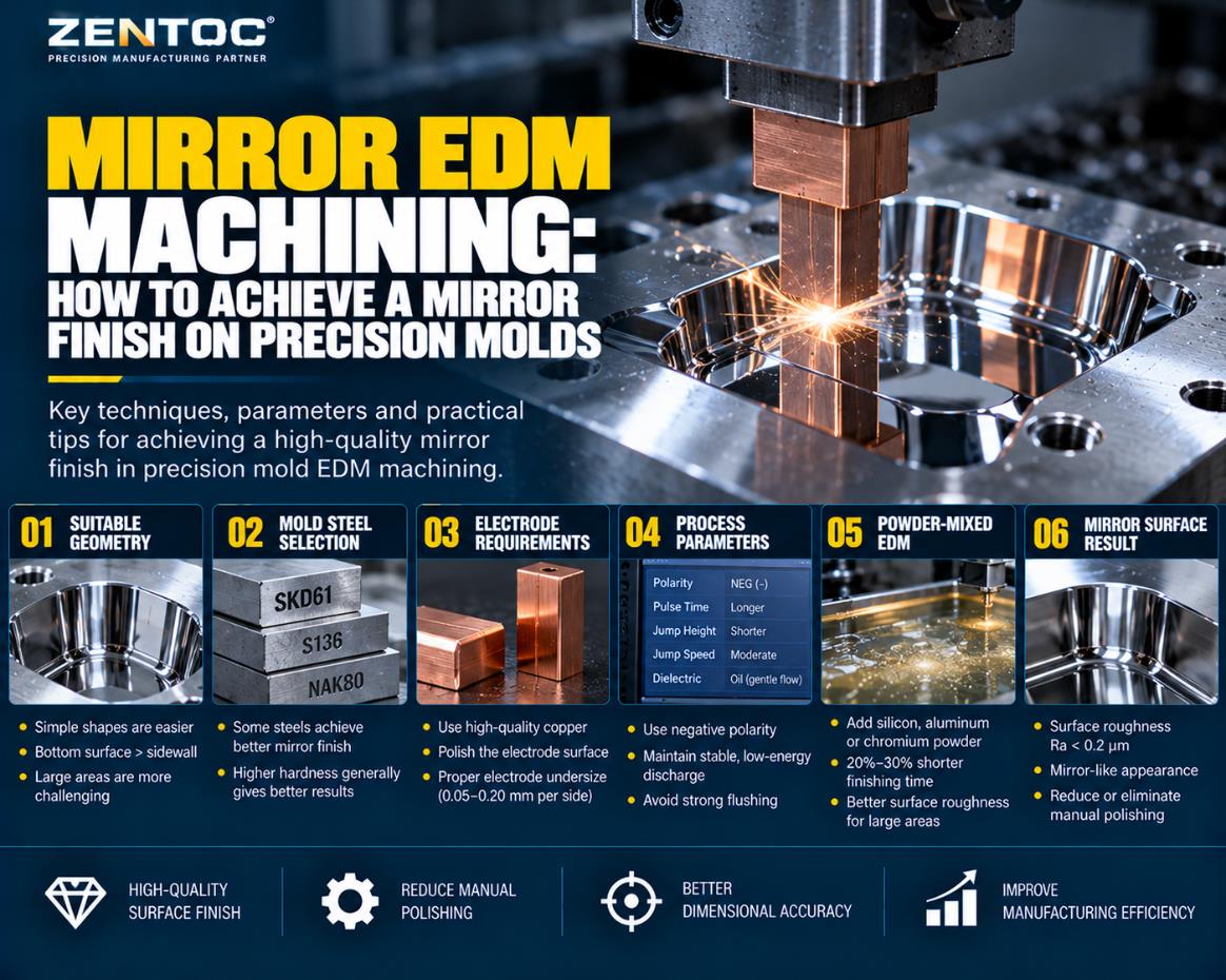
A mirror EDM surface generally refers to an EDM finish with surface roughness below Ra 0.2 micrometers. Under suitable conditions, it can reduce or eliminate manual polishing while improving consistency, dimensional accuracy and manufacturing efficiency.
1. What Is Mirror EDM Machining?
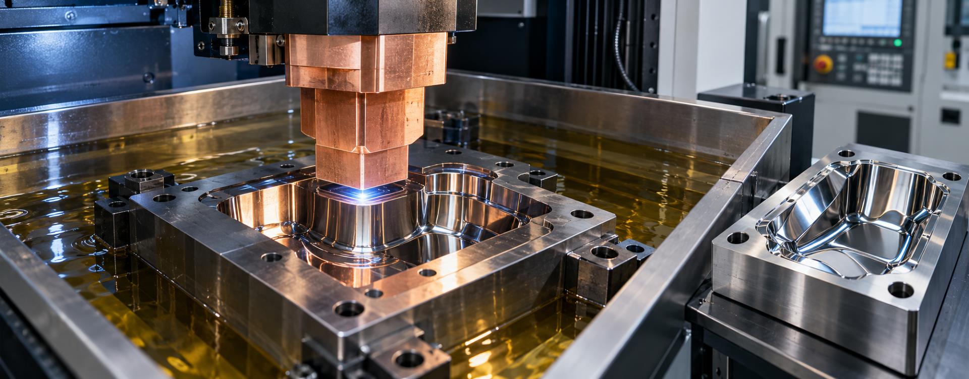
Mirror EDM uses a sequence of progressively lower-energy electrical discharges to smooth the microscopic peaks left by earlier machining stages. Stable discharge conditions and a uniform carbonaceous surface layer help create a consistent reflective finish.
1.1 Surface Target
The typical mirror-finish reference is surface roughness below Ra 0.2 micrometers with a visible reflective effect.
1.2 Material Removal
Final mirror finishing removes very little material. Its primary purpose is to improve roughness rather than substantially change dimensions.
1.3 Process Sequence
Rough EDM, intermediate finishing and low-energy mirror finishing are coordinated through suitable electrodes and allowances.
2. Which Mold Geometries Suit Mirror EDM?
Geometry affects debris movement, discharge uniformity and carbon-layer formation. Mirror EDM should be evaluated before it is selected as the final finishing process.
2.1 Simple Shapes
Simple geometry is easier to finish uniformly. Circular features are especially suitable.
2.2 Bottoms vs. Sidewalls
Cavity bottoms are generally easier to mirror-finish than vertical sidewalls.
2.3 Deep Cavities
Greater depth makes sidewall finishing and stable dielectric conditions more difficult.
2.4 Large Areas
A larger discharge area requires tighter control to maintain uniform roughness and reflectivity.
2.5 Complex Corners
Sharp transitions and complex curves may show less uniform reflection than open, simple surfaces.
2.6 Open or Hollow Regions
Open sections and hollow areas may be less favorable for consistent mirror finishing.
3. Selecting Mold Steel for Mirror EDM
Steel composition, hardness and metallurgical uniformity influence the final EDM surface. The following ratings summarize the machining experience in the source and are not universal material specifications.
| Category | Mold Material | Mirror EDM Performance |
|---|---|---|
| A | SKD61 | Excellent |
| A | STAVAX / S136 | Excellent |
| A | PD555 | Excellent |
| A | NAK80 | Excellent |
| A | 718H | Excellent |
| B | SKS3 | Good |
| B | SKH9 | Good |
| B | HPM38 | Good |
| B | S55C | Good |
| B | H13 | Good |
| B | XW10 | Slightly inferior |
| C | SKD11, NAK55, HPM1, DH2F | Poor |
| D | Brass, aluminum, cemented carbide | Orange-peel-like finish |
Higher mold-steel hardness is generally associated with better mirror EDM results, but actual performance must be validated for the exact grade, heat treatment and workpiece.
4. Mirror EDM Electrode Requirements
Electrode material, finish, undersize and positioning accuracy directly affect roughness, dimensional control and process stability.
4.1 Electrode Material
High-purity, uniform copper with low impurity content and predictable wear is a common choice. Poor copper can cause wear and surface wrinkling.
4.2 Electrode Surface
Remove tool marks, scratches and defects because electrode imperfections may transfer to the mold surface.
4.3 Electrode Undersize
Typical single-side undersize is 0.05-0.20 mm. A conventional finishing reference is about 0.10 mm per side.
4.4 Application Adjustment
Smaller areas and high-accuracy contours may use less undersize, while powder-mixed EDM may require slightly more.
4.5 Multiple Electrodes
High-quality finishing commonly uses several electrodes, requiring consistent manufacturing and wear control.
4.6 Positioning Repeatability
Reference-ball measurement and quick-change clamping systems help maintain position when electrodes are replaced.
5. Controlling Mirror EDM Machining Allowance
5.1 Rough EDM
A roughing electrode and higher discharge energy remove material efficiently while controlling geometry and position.
5.2 Finish EDM
A finishing electrode and progressively lower current improve the surface. Depth feeding treats the bottom, while orbital movement improves sidewalls.
5.3 Larger Allowance
More remaining stock can support reliable cleanup but increases finishing time.
5.4 Smaller Allowance
Less stock improves speed but may leave pinholes, uneven reflection or inconsistent texture.
Ideally, each finishing stage smooths the roughness created by the previous condition rather than removing large amounts of new material. A slightly larger allowance can improve process reliability when variables are uncertain.
6. Optimizing Mirror EDM Discharge Parameters
The source describes mirror EDM with negative polarity and stable, low-energy discharge settings. Electrical parameters must be coordinated with motion and dielectric control.
6.1 Discharge Duration
Longer discharge duration can help maintain the controlled finishing condition described in the source.
6.2 Electrode Jump Height
Use a shorter jump height because final finishing produces relatively little debris.
6.3 Electrode Jump Speed
Moderate or slower jumping helps avoid disturbing continuous low-energy discharge.
6.4 Machining Time
Stop when the required roughness is achieved. Timed machining can be selected from validated process experience.
6.5 Dielectric Circulation
Use submerged oil machining with slight circulation around the work area. Avoid aggressive flushing.
6.6 Carbon Layer Stability
Minimize unnecessary stops and avoid removing the thin carbonaceous layer during finishing.
7. Powder-Mixed EDM for Large Areas
Powder-mixed EDM, or PMEDM, adds fine conductive or semiconductive powder to dielectric fluid to modify discharge behavior and improve surface uniformity.
7.1 Powder Additives
Silicon, aluminum, chromium and other suitable powders are referenced for finishing applications.
7.2 Surface Improvement
Distributed discharge can produce better roughness and a more uniform mirror-like appearance on larger areas.
7.3 Finishing Efficiency
The source reports an approximate 20-30% finishing-time reduction under comparable electrical settings.
7.4 Concentration Control
A suitable circulation and dispersion system keeps powder concentration and distribution uniform.
The actual benefit depends on the machine, powder, dielectric system, workpiece, electrode and validated process settings.
8. Key Factors Affecting Mirror EDM Surface Quality
| Key Factor | Recommended Approach |
|---|---|
| Workpiece geometry | Prefer simple shapes; deep cavities and large areas require extra control |
| Mold material | Select steel with proven mirror EDM performance |
| Electrode material | Use uniform, low-impurity material with predictable wear |
| Electrode finish | Remove tool marks, scratches and surface defects |
| Electrode undersize | Typically 0.05-0.20 mm per side depending on the application |
| Electrode positioning | Maintain repeatable clamping and alignment when changing electrodes |
| Machining allowance | Balance cleanup reliability with finishing efficiency |
| Discharge control | Maintain stable, low-energy conditions through the final stages |
| Electrode jumping | Avoid excessive height, speed and frequency |
| Dielectric flushing | Use gentle circulation instead of aggressive flushing |
| Powder-mixed EDM | Consider for larger areas and improved finishing uniformity |
9. Advantages of Mirror EDM in Precision Mold Manufacturing
9.1 Reduced Manual Polishing
Reflective surfaces can be produced directly in the EDM machine for suitable cavities and materials.
9.2 Improved Consistency
Controlled discharge can produce a more uniform finish than difficult manual work on complex geometry.
9.3 Better Dimensional Control
Reducing hand polishing helps preserve precision-machined contours, edges and dimensions.
9.4 Manufacturing Efficiency
Optimized finishing and PMEDM can offset long EDM time by reducing later polishing operations.
Conclusion
Achieving a mirror EDM finish below Ra 0.2 micrometers requires more than selecting low discharge energy. Mold steel, cavity geometry, electrode quality, undersize, allowance, positioning, dielectric circulation and discharge stability all contribute to the result.
When these factors are optimized, mirror EDM can reduce manual polishing, maintain mold accuracy and improve the consistency and efficiency of precision mold manufacturing.
Mirror EDM Machining FAQ
What surface roughness is considered mirror EDM?
A common reference is an EDM surface below Ra 0.2 micrometers with a visible reflective appearance.
Which geometry is easiest to mirror-finish by EDM?
Simple shapes, especially circular features and cavity bottoms, are generally easier than deep sidewalls, sharp corners and large areas.
What is a typical mirror EDM electrode undersize?
The source gives a typical single-side range of 0.05-0.20 mm, with about 0.10 mm per side commonly used for conventional finishing electrodes.
Why should strong dielectric flushing be avoided?
Aggressive flushing can disturb stable micro-discharges and the surface condition required for uniform mirror finishing.
When is powder-mixed EDM useful?
It is especially useful for large-area finishing where conventional EDM may struggle to produce a uniform reflective surface efficiently.
Need Precision EDM and Mold Manufacturing?
Zentoc provides precision mold manufacturing, EDM machining, CNC machining and customized production solutions.
Contact Zentoc