
Uneven surface gloss is an uncommon and sometimes confusing injection molding appearance defect. Bright and dull areas can appear on the same molded component even when the corresponding mold surfaces have essentially the same finish. In some cases, the boundary moves when molding parameters change.
The defect is best understood through mold-surface replication. Cavity pressure, material shrinkage, cooling, flow speed and part geometry determine how closely the polymer remains in contact with the mold while the surface solidifies.
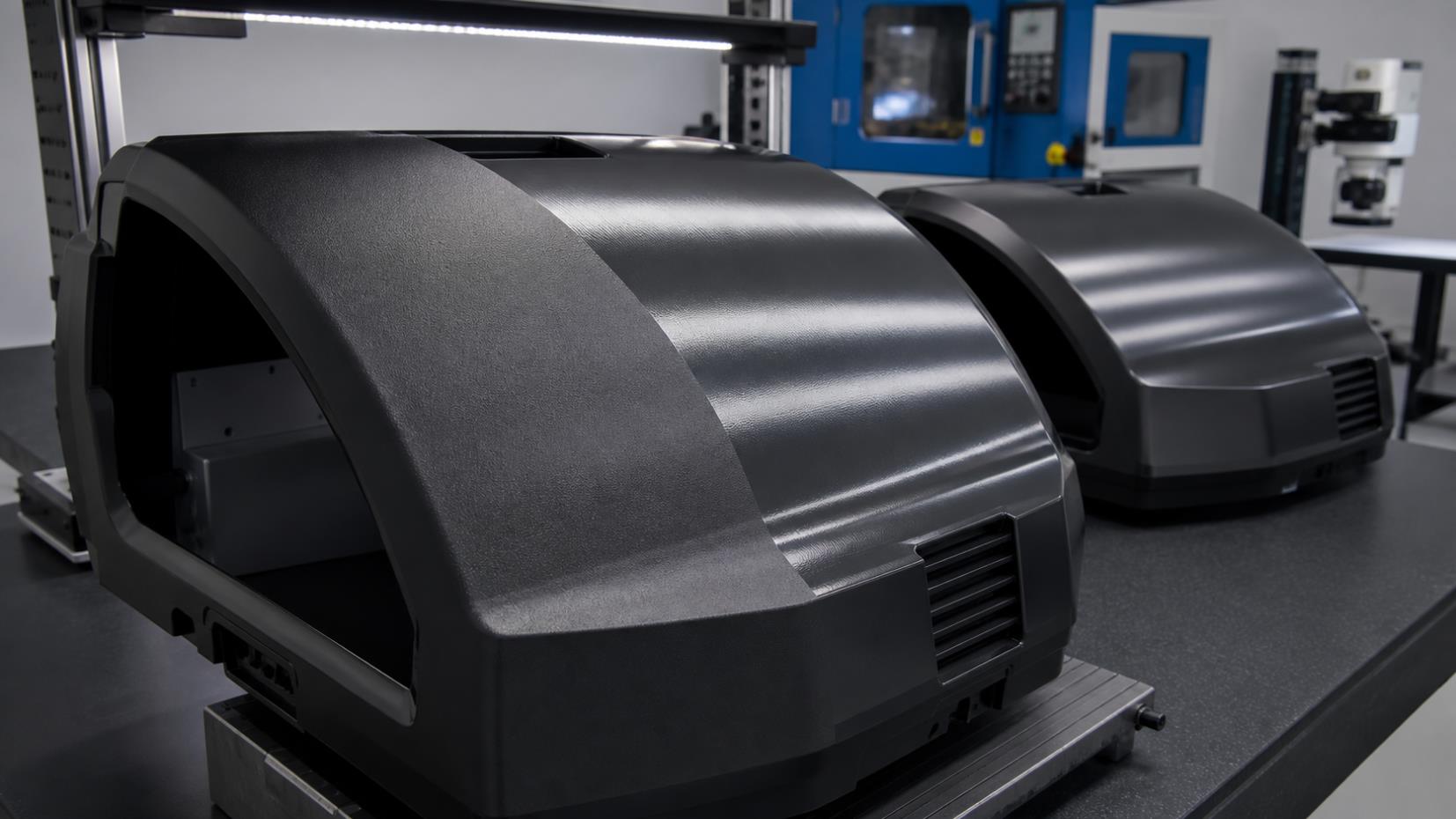
1. What Is Uneven Surface Gloss?
Different regions of the same injection molded part show visible brightness differences even though the mold texture appears uniform. The issue is more common on large parts, long flow paths, high-shrinkage materials and surfaces molded at medium or relatively low mold temperatures.
Common Appearance
Gloss difference near and far from the gate
Localized bright or dull patches
Neighboring areas with different gloss
A boundary that shifts after parameter changes
Why Diagnosis Is Difficult
The mold may show no obvious roughness difference. Because parameter changes alter pressure and cooling inside the cavity, the visible boundary can move instead of simply disappearing.
2. Three Related Surface-Gloss Phenomena
Overall Gloss Changes
Higher injection speed and mold temperature often create a brighter overall surface, while lower settings may produce a duller result.
Dark Areas Opposite Ribs
A rib on the rear surface changes local flow, pressure, cooling and shrinkage, sometimes creating a dull area on the cosmetic side.
Bright and Dull Regions Together
Different areas reproduce the mold surface with different accuracy because contact pressure and shrinkage are not uniform.
3. Mold Surface Replication and Gloss
On a polished mold, suitable melt temperature, mold temperature, injection speed and holding pressure keep hot polymer in close contact with the cavity while it cools. Better replication creates a smoother molded surface that reflects light more uniformly and generally appears brighter.
Good Replication
Adequate thermal condition
Sufficient cavity and holding pressure
Stable contact during surface solidification
Accurate reproduction of the cavity finish
Poor Replication
If the polymer surface pulls away before solidification, heat transfer falls. Local reheating, micro-bubbling or shrinkage can increase microscopic roughness and change reflected light.
4. Why Does Plastic Separate From the Mold?
Separation becomes possible when the outward force created by cavity pressure is lower than the inward contraction caused by cooling shrinkage.
High-Shrinkage Material
Greater contraction creates a stronger tendency to pull away from the cavity surface, increasing the risk of poor replication.
Low Pressure
Insufficient injection or holding pressure reduces the force maintaining surface contact during filling and cooling.
Low Temperature
Unsuitable melt or mold temperature can freeze the surface too early and reduce the ability to reproduce fine cavity detail consistently.
5. How Cavity Pressure Creates Bright and Dull Areas
Cavity pressure decreases and redistributes as polymer travels through the mold. High-pressure regions remain more firmly pressed against the surface and normally replicate it better. Lower-pressure regions are more likely to shrink away and appear dull on smooth parts.
Near Gate vs. End of Fill
Pressure is generally higher near the gate and lower toward the end of a long flow path. Large components can therefore show a strong gloss gradient.
Wall Thickness Changes
Thin and thick regions cool and transmit pressure differently. Under relevant conditions, a thin region may appear bright while an adjacent thick area looks dull.
Flow Around Corners
Direction changes, ribs and divided flow alter local pressure. Straight-flow areas may replicate differently from turning or hesitation regions.
Areas Opposite Ribs
Ribs influence local flow, cooling and shrinkage, which can make their location visible through gloss even without an obvious dimensional defect.
6. Typical Uneven Gloss Patterns
| Higher-gloss tendency | Lower-gloss tendency | Likely reason |
|---|---|---|
| Near the gate | Far from the gate | Pressure loss along the flow path |
| Thin-wall area | Thick-wall area | Different pressure, cooling and shrinkage behavior |
| Straight or flat flow | Flow-turning area | Local pressure loss and flow redirection |
| Normal flat surface | Surface opposite a rib | Rib-driven cooling, pressure and shrinkage effects |
| Normal-flow region | Hesitation-flow region | Reduced flow-front speed and early cooling |
| High-speed injection region | Low-speed injection region | Different surface replication during filling |
These patterns are diagnostic clues, not absolute rules. Actual appearance depends on resin, texture, geometry, gate design, process settings and thermal balance.
7. Multi-Stage Injection Speed and Gloss Boundaries
When different cavity regions fill at different programmed speeds, their surface appearance may also differ. A faster-filled area may appear brighter while a slower-filled region appears duller on a smooth mold.
8. What About Textured Mold Surfaces?
A textured cavity contains microscopic peaks and valleys that scatter light. Better replication does not always create the same perceived-brightness change as it does on a polished mold. The visual relationship can be weaker or even reversed.
Polished Surface
More accurate replication usually produces a smoother, brighter plastic surface.
Textured or Matte Surface
Replication changes the fidelity of microscopic texture. Evaluate gloss together with texture depth, viewing angle and approved appearance standard.
9. How to Troubleshoot Uneven Surface Gloss
Map the defect: mark the bright and dull boundary and compare it with gate position, flow path, ribs, corners and thickness changes.
Review injection speed: check whether fast, slow or hesitation regions match the appearance pattern.
Verify filling pressure: ensure enough injection pressure is available without masking a gate or venting problem.
Optimize holding: review holding pressure, time and transfer position to maintain contact during shrinkage.
Check mold temperature: measure actual cavity-side temperature and confirm uniformity across circuits.
Check melt condition: verify melt temperature, residence time and material preparation.
Consider resin shrinkage: compare behavior with the qualified material grade and lot.
Evaluate gate and flow length: long paths and undersized gates can create large pressure differences.
Review part geometry: investigate wall transitions, ribs, flow dividers and hesitation zones.
Use controlled trials: change one parameter group at a time and document how the boundary moves.
10. Practical Correction Priorities
Process
Balance injection-speed stages
Maintain adequate holding pressure
Optimize melt and mold temperatures
Verify transfer and cushion stability
Mold
Improve gate location or size
Balance cooling circuits
Check venting at end of fill
Confirm cavity texture consistency
Product and Material
Reduce abrupt wall changes
Review rib geometry
Shorten difficult flow paths where possible
Validate lower-shrinkage material options
Frequently Asked Questions
Can uneven gloss occur when the mold texture is uniform?
Yes. Different cavity regions can reproduce the same mold texture differently because pressure, temperature, cooling and shrinkage vary throughout the part.
Why does the bright and dull boundary move?
Changes in injection speed, holding pressure or temperature shift the internal pressure and solidification pattern, so the location where surface contact is lost can also shift.
Why are large parts more susceptible?
Long flow paths create greater pressure loss and thermal variation between the gate and end-of-fill regions.
Does a brighter surface always mean better replication?
Generally on polished molds, but not necessarily on textured surfaces. Texture geometry changes the way light is scattered and perceived.
Need Consistent Injection-Molded Surface Quality?
Zentoc supports plastic part development, mold manufacturing, injection molding and process optimization for cosmetic and functional components.
Contact Zentoc