Indexable inserts are replaceable cutting elements used in CNC turning, milling and other machining operations. Their standardized shapes, materials, coatings and chipbreaker geometries allow manufacturers to match cutting performance to the workpiece and application.
This guide explains indexable cutting tool fundamentals, insert materials, ISO workpiece groups and the principal positions used in cutting tool insert designation systems.
1. Basic Concept of Indexable Cutting Tools
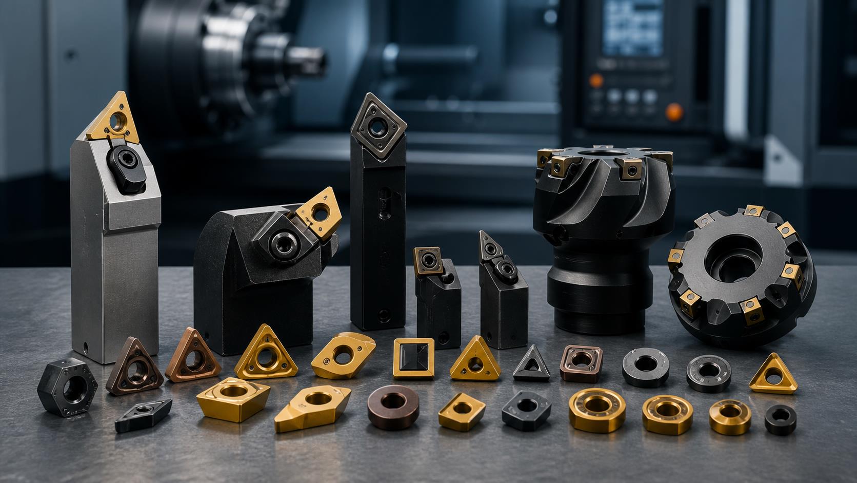
An indexable cutting tool uses a premanufactured polygonal insert with multiple cutting edges mechanically clamped to a reusable tool body. When one edge becomes dull, the insert is indexed or replaced, placing a fresh edge in the working position.
2. Indexable Tools vs. Brazed and Solid Tools
2.1 Multiple Cutting Edges
Most inserts provide at least two usable cutting edges. Some special designs, including certain ball-nose inserts, are replaced rather than indexed.
2.2 Repeatable Edge Position
After indexing, the active edge returns to the intended position and maintains the specified cutting geometry relative to the tool body.
3. Advantages of Indexable Inserts
3.1 Flexible Cutting Performance
The insert is an independent functional component, allowing material, coating and geometry to be optimized for the workpiece.
3.2 Mechanical Clamping
Clamping avoids brazing limitations and makes insert replacement fast and predictable.
3.3 Higher Machine Utilization
Repeatable edge positioning reduces tool-setting and changeover time in CNC machining.
3.4 Production Economy
Efficient cutting and reusable tool bodies can improve productivity while reducing tool-body material and manufacturing cost.
4. Carbide Insert Fundamentals and Coatings
4.1 Carbide Production
Tungsten and cobalt powders are mixed, pressed and sintered. Finishing inserts may be ground before coating.
4.2 Aluminum Oxide
Aluminum oxide, written as Al2O3 in this page for backend compatibility, mainly improves wear resistance.
4.3 Titanium Nitride
Titanium nitride, TiN, supports resistance to edge chipping and provides a characteristic coating appearance.
5. Six Common Cutting Tool Insert Materials
| Material | Typical characteristics and application |
|---|---|
| Carbide | General-purpose substrate used across many machining operations. |
| Coated carbide | Combines a carbide substrate with wear-resistant or application-specific coatings. |
| Cermet | Hard, brittle and wear resistant; primarily used for finishing. |
| Ceramic | Used for hard materials, with the source citing approximately 45 to 55 HRC. |
| CBN | Used for hardened materials above about 55 HRC; more common in turning than milling. |
| PCD | Often selected for mirror finishing of aluminum alloys and other suitable nonferrous materials. |
6. ISO P M K N S H Workpiece Material Groups
| Code | Workpiece materials |
|---|---|
| P | Plain carbon steels and alloy steels |
| M | Stainless steels |
| K | Cast iron and similar materials with moderate hardness and good chip breaking |
| N | Soft nonferrous metals such as copper and aluminum |
| S | Difficult-to-machine metals such as heat-resistant alloys |
| H | High-hardness materials such as hardened steel |
7. Indexable Insert Designation Rules
The cited Chinese national designation follows the main ISO positions and adds a hyphen plus an additional code for chipbreaker form and width. The first seven elements define the principal insert parameters; later positions are used where required by the system or manufacturer.
| Position | Meaning | Selection purpose |
|---|---|---|
| 1 | Insert shape | Defines geometry and nose angle |
| 2 | Main cutting-edge clearance angle | Determines relief and holder compatibility |
| 3 | Insert tolerance | Defines dimensional accuracy |
| 4 | Fixing method and chipbreaker configuration | Defines clamping and face form |
| 5 | Main cutting-edge length | Defines nominal insert size |
| 6 | Insert thickness | Matches pocket and strength requirement |
| 7 | Nose radius or corner configuration | Affects strength, finish and geometry |
| 8 | Groove geometry | Indicates finishing, semi-finishing or roughing use |
| 9 | Cutting direction or manufacturer-reserved code | Depends on the applicable designation system |
| 10 | Insert material or added national-standard information | Brand and standard usage must be confirmed |
8. Insert Shape and Clearance-Angle Codes
8.1 Insert Shape Codes
| Code | Shape | Nose angle | Code | Shape | Nose angle |
|---|---|---|---|---|---|
| A | Parallelogram | 85 degrees | B | Rhombus | 82 degrees |
| C | Rhombus | 80 degrees | D | Rhombus | 55 degrees |
| E | Regular hexagon | 75 degrees | H | Regular hexagon | 120 degrees |
| K | Parallelogram | 55 degrees | L | Rectangle | 90 degrees |
| M | Rhombus | 86 degrees | O | Regular octagon | 135 degrees |
| P | Regular pentagon | 108 degrees | R | Round | 0 degrees |
| S | Square | 90 degrees | T | Equilateral triangle | 60 degrees |
| V | Rhombus | 35 degrees | W | Equal-sided unequal-angle hexagon | 80 degrees |
8.2 Clearance-Angle Codes
| Code | A | B | C | D | E | F | G | N | P |
|---|---|---|---|---|---|---|---|---|---|
| Normal clearance | 3 degrees | 5 degrees | 7 degrees | 15 degrees | 20 degrees | 25 degrees | 30 degrees | 0 degrees | 11 degrees |
Different clearance angles require compatible toolholders. A positive-clearance insert has upper and lower faces of different sizes.
9. Cutting-Edge Length, Thickness and Nose Radius
9.1 Cutting-Edge Length
Two digits identify the integer portion of the theoretical edge length. For example, 16.5 mm becomes 16 and 9.525 mm becomes 09. For round inserts, the referenced dimension is diameter.
9.2 Thickness Codes
| Code | 02 | T2 | 03 | T3 | 04 | 05 | 06 |
|---|---|---|---|---|---|---|---|
| Thickness mm | 2.38 | 2.78 | 3.18 | 3.97 | 4.76 | 5.56 | 6.35 |
9.3 Nose-Radius Codes
| Code | R02 | 04 | 08 | 12 |
|---|---|---|---|---|
| Nose radius mm | 0.2 | 0.4 | 0.8 | 1.2 |
For turning inserts, the two-digit code commonly equals ten times the radius. Round inserts use radius code 00, which may be omitted in the referenced system.
10. Edge Geometry, Chipbreaker and Cutting Direction
| Code | Cutting-edge geometry |
|---|---|
| F | Sharp cutting edge |
| E | Rounded cutting edge |
| T | Negative chamfered cutting edge |
| S | Negative chamfered and rounded cutting edge |
Chipbreaker groove designs indicate finishing, semi-finishing or roughing use and vary by brand. A groove may be unnecessary for brittle materials or naturally broken chips, but is generally needed for tougher materials where chip control is important.
| Code | Cutting direction |
|---|---|
| R | Right-hand cutting |
| L | Left-hand cutting |
| N | Right- and left-hand cutting |
Indexable Insert FAQ
What is an indexable insert?
It is a replaceable cutting element with one or more usable edges that is mechanically clamped to a reusable tool body.
What are the ISO P M K N S H groups?
They classify major workpiece-material families: steel, stainless steel, cast iron, nonferrous metals, heat-resistant alloys and hardened materials.
Why do insert coatings matter?
Coatings can improve wear resistance, edge durability, heat management and application performance.
Can inserts from different brands use the same grade code?
Not necessarily. The first standard designation positions may align, but chipbreaker and material-grade codes are commonly manufacturer-specific.
Need CNC Machined Components?
Zentoc provides precision CNC machining and custom manufacturing for metal and plastic parts.
Contact Zentoc