
During CNC milling, many factors can contribute to machining errors. Among them, tool radial runout is one of the most important influences on dimensional accuracy, surface geometry, cutting stability, and tool life.
When runout is excessive, the cutting edges of a multi-flute tool do not share the load evenly. One flute may remove more material than the others, causing unstable cutting forces, uneven wear, vibration, and inconsistent surface quality.
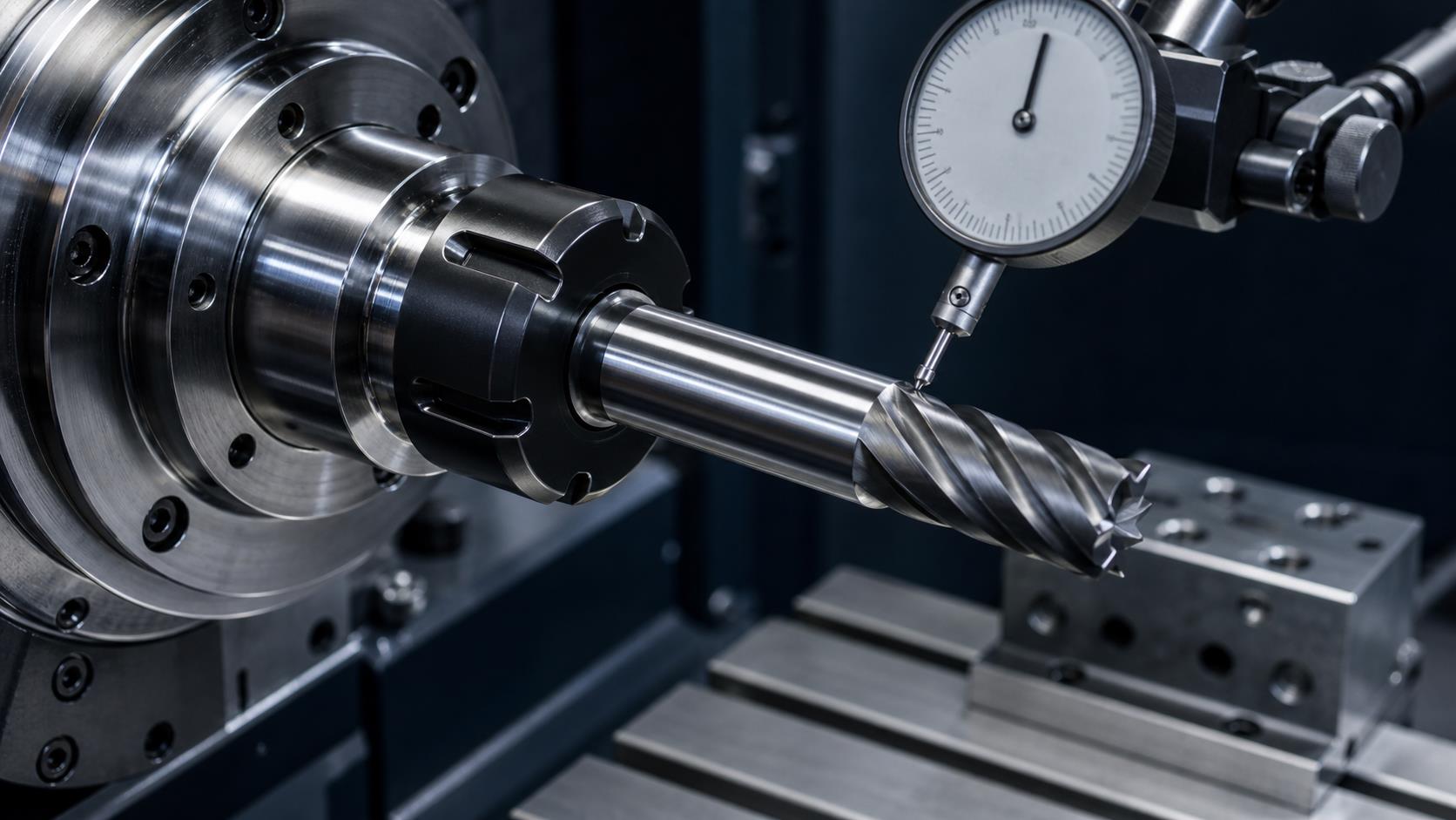
What Causes CNC Milling Tool Radial Runout?
Measured tool runout can originate from spindle error, taper or holder contamination, holder accuracy, collet condition, improper clamping, tool shank variation, and excessive assembly length. During actual machining, radial cutting forces add dynamic tool deflection and vibration to these geometric errors.
As radial force increases, a flexible tool setup bends farther away from its intended axis. This changes the effective cutting position and chip load of each flute, making the process progressively less stable.
The effects can include:
Dimensional and form errors
Poor or inconsistent surface roughness
Uneven wear between cutting flutes
Reduced tool life and premature chipping
Higher vibration and cutting noise
Unstable multi-flute cutting performance
Core principle: Reduce radial cutting forces, eliminate assembly errors, and increase the rigidity of the complete spindle–holder–tool system.
1. Use Sharp Cutting Tools
A sharp cutting edge reduces cutting resistance and helps limit radial forces and vibration. A larger positive rake angle generally makes the edge cut more freely, while a suitable clearance angle reduces rubbing between the tool flank and the elastically recovered workpiece surface.
However, excessively large rake and clearance angles can weaken the edge and reduce its ability to conduct heat. Tool geometry should therefore match the operation:
Rough Machining
Smaller rake and clearance angles can provide stronger cutting edges for higher loads and interrupted engagement.
Finishing
Sharper, more positive geometries can reduce cutting forces, tool deflection, and radial runout effects.
2. Use a More Rigid Cutting Tool Setup
Tool rigidity is one of the most effective ways to limit cutting-force-induced deflection. Two practical actions are increasing shank diameter and reducing tool overhang.
Increase Tool Shank Diameter
Under the same radial cutting force, a larger shank diameter provides substantially greater bending stiffness. Even a moderate diameter increase can significantly reduce deflection.
Reduce Tool Overhang Length
A long overhang behaves like a flexible cantilever. As projection increases, the cutting end deflects more easily and becomes more sensitive to vibration.
Can reduce radial deflection by approximately 50% under comparable conditions.
Can also reduce radial deflection by approximately 50% in an equivalent setup.
These figures are useful engineering illustrations; actual improvement depends on geometry, material, holder, load, and boundary conditions.
3. Keep the Tool Rake Face Smooth
A smooth rake face reduces friction as chips flow across the cutting tool. Lower friction decreases cutting forces and heat generation, helping reduce tool deflection and dynamic radial displacement.
A well-finished cutting edge and rake surface can improve:
Chip flow and evacuation
Cutting-force consistency
Machined surface finish
Resistance to built-up edge
Overall cutting stability
Predictability of tool performance
4. Keep the Spindle Taper and Tool Holder Clean
Small chips, dust, oil residue, or damage between mating surfaces can tilt the holder and create measurable runout at the cutting edge. The effect becomes larger as tool projection increases.
Before installation:
Clean the machine spindle taper thoroughly.
Inspect and clean the tool holder taper.
Remove chips and debris from collet and nut contact surfaces.
Check the tool shank for dirt, burrs, or damage.
Use the shortest practical holder and tool projection.
Apply the specified, consistent clamping torque.
Both excessive and insufficient tightening can affect clamping behavior and tool positioning. Follow the holder manufacturer's torque and assembly recommendations.
5. Select an Appropriate Cutting Depth
When Cutting Depth Is Too Small
The cutting edge may rub or plough instead of forming a stable chip, especially if engagement approaches the tool's edge radius. This can cause changing forces, vibration, poor finish, and unstable runout behavior.
When Cutting Depth Is Too Large
Cutting forces rise substantially, increasing tool deflection and flute-to-flute load variation. Surface errors, chatter, and edge failure become more likely.
Best practice: Select radial and axial engagement together with feed per tooth and cutting speed so every flute forms a controlled chip without overloading the tool.
6. Use Climb Milling During Finishing
Climb milling often improves finishing stability because the cutting edge enters at maximum chip thickness and exits toward zero. This can reduce rubbing and produce a cleaner surface when the machine and feed system have minimal backlash.
On machines with significant backlash, climb milling can pull the table into the cutter and cause irregular motion. Machine condition must therefore be considered.
Conventional milling may still be selected for some roughing situations or older machines, while climb milling is generally preferred for accurate finishing on rigid CNC equipment.
7. Use Cutting Fluid Properly
Appropriate cutting fluid can reduce friction and help stabilize cutting. Water-based coolants primarily remove heat, although their lubrication performance depends on formulation and concentration.
Lubricating cutting oils can reduce friction at:
The interface between the rake face and flowing chip
The interface between the tool flank and machined surface
Lower friction can reduce cutting forces, built-up edge, and dynamic tool deflection. Fluid selection should remain compatible with the workpiece, tool coating, machine, process speed, and environmental requirements.
CNC Tool Runout Inspection Checklist
Measure runout at the tool shank and near the cutting edge.
Clean the spindle taper, holder, collet, nut, and tool shank.
Rotate or replace individual components to isolate the source.
Inspect the collet and holder for wear, fretting, or damage.
Confirm correct clamping torque and tool insertion depth.
Reduce tool and holder overhang wherever possible.
Check spindle condition if multiple holders show similar runout.
Review cutting forces, engagement, and vibration during machining.
Frequently Asked Questions
What is CNC milling tool radial runout?
Radial runout is the variation in a tool's radial position as it rotates. It causes cutting edges to follow different paths instead of rotating concentrically around the intended spindle axis.
How does runout affect a multi-flute end mill?
The flute farthest from the rotation axis removes more material and carries more load. Other flutes may cut less or rub, leading to uneven wear, poor finish, and early failure.
Where should tool runout be measured?
Measure at a clean, round tool shank surface and, when practical, near the cutting edge. Runout at the tool tip is often higher because holder error is amplified by projection.
Can excessive tightening cause runout?
Yes. Incorrect torque can distort or improperly seat some holder components. Always use the manufacturer's specified assembly procedure and torque.
Does a larger tool always reduce runout?
A larger diameter increases bending stiffness, but geometric runout from the spindle, holder, collet, or tool assembly must still be corrected. Rigidity and concentricity are related but different issues.
Conclusion
Tool radial runout is a major factor affecting CNC machining accuracy, surface quality, flute loading, and tool life. It cannot always be eliminated completely, but its effects can be greatly reduced through sharper tool geometry, greater rigidity, shorter overhang, clean interfaces, correct clamping, stable cutting parameters, suitable milling direction, and proper lubrication.
Combining accurate spindle and holder assembly with appropriate tooling and optimized machining conditions produces higher precision, better surface finishes, more uniform wear, and more reliable production.