
Vibration is a common challenge in CNC milling. It may originate from the cutting tool, tool holder, machine spindle, workpiece, fixture, or unsuitable cutting parameters. If it is not properly controlled, vibration can reduce dimensional accuracy, damage the surface finish, shorten tool life, and lower machining efficiency.
Understanding the source of vibration is the first step toward solving it. This guide explains the most common causes of CNC milling vibration and provides practical countermeasures for a more stable machining process.
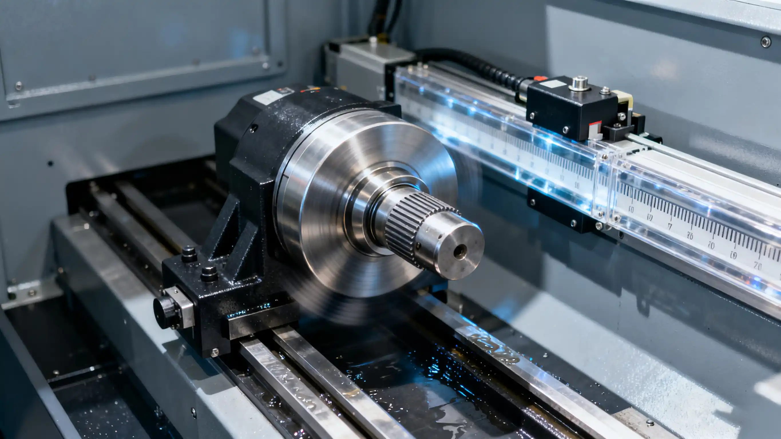
Why Does Vibration Occur in CNC Milling?
Milling is an interrupted cutting process. As each cutting edge enters and exits the workpiece, the cutting force changes continuously. When the rigidity or damping capacity of the machining system is insufficient, these force variations can cause vibration or regenerative chatter.
The cutter, holder, spindle, workpiece, and fixture form one connected system. This means several factors may contribute to vibration at the same time.
1. Poor Fixture Rigidity
An unstable fixture allows the workpiece to move or deflect under cutting forces, resulting in chatter marks, dimensional errors, excessive noise, and inconsistent tool life.
Recommended solutions:
Analyze the direction of cutting forces and add support where it is most effective.
Improve the fixture design and reduce unsupported workpiece areas.
Reduce the axial depth of cut (ap) to lower cutting forces.
Use coarse-pitch or unequal-pitch milling cutters.
Select sharp, light-cutting geometries with a smaller nose radius and shorter parallel land.
Consider fine-grain uncoated or lightly coated inserts where appropriate.
Avoid machining areas without sufficient support to resist cutting forces.
Practical tip: Position clamping points as close to the machining area as possible without deforming the workpiece.
2. Workpieces with Poor Axial Rigidity
Thin walls, slender parts, and long unsupported sections are particularly sensitive to axial cutting forces. Even a rigid machine may produce vibration if the workpiece itself deflects during milling.
Recommended solutions:
Use a positive-rake square shoulder cutter with a 90° entering angle.
Select sharp, light-cutting inserts such as suitable L-type geometries.
Reduce the axial depth of cut and use a smaller nose radius.
Choose a coarse-pitch, unequal-pitch milling cutter.
Inspect inserts for wear or edge damage.
Check the tool holder and cutter for excessive runout.
Improve tool clamping and workpiece support.
3. Excessive Tool Overhang
Long tool overhang is one of the most frequent causes of milling chatter. As overhang increases, tool rigidity decreases rapidly and the cutting system becomes more likely to deflect.
Recommended solutions:
Keep tool overhang as short as the workpiece geometry allows.
Use a coarse-pitch or unequal-pitch cutter.
Choose a 45° entering angle, larger nose radius, or round inserts to balance radial and axial forces.
Increase feed per tooth (fz) within the safe operating range.
Use sharp, light-cutting insert geometries.
Reduce the axial depth of cut.
Apply climb milling during finishing operations.
Use a rigid modular interface or vibration-damped tooling for long-reach machining.
For solid carbide end mills, try fewer flutes and a larger helix angle.
4. Square Shoulder Milling with a Low-Rigidity Spindle
Square shoulder milling can generate significant radial cutting forces. On machines with a flexible spindle, these forces may cause tool deflection and unstable cutting.
Recommended solutions:
Select the smallest cutter diameter that can perform the operation efficiently.
Use light-cutting cutters and inserts with sharp cutting edges.
Apply climb milling when the machine and setup permit it.
Check spindle deflection against the machine tool's acceptable limits.
Inspect spindle bearings and the tool interface if abnormal movement is detected.
5. Unstable Table Feed
Irregular table movement causes variations in chip thickness and cutting load. It is especially common in machines with backlash, worn feed components, or poorly adjusted drive systems.
Recommended solutions:
Use climb milling where appropriate.
Inspect and tighten the machine feed mechanism.
On CNC machines, check the feed screw, servo system, and backlash compensation.
On conventional machines, adjust the table locking mechanism or replace worn ball screws.
Verify that the programmed feed remains stable throughout the cutting cycle.
6. Unsuitable Cutting Parameters
Cutting speed, feed per tooth, and depth of cut directly influence milling stability. Parameters that are too aggressive—or too conservative—can place the operation inside an unstable vibration range.
Reduce cutting speed (vc) if chatter occurs.
Increase feed per tooth (fz) to form a proper chip instead of rubbing.
Adjust axial depth of cut (ap).
Reduce radial engagement when machining deep cavities or thin walls.
Try a clearly different spindle speed rather than making only a very small change.
Important: Increasing feed per tooth can improve stability when the original feed causes rubbing, but all changes must stay within safe tool and machine limits.
7. Poor Overall Machining Stability
Sometimes vibration does not come from a single component. Instead, it results from the combined flexibility of the tool, holder, spindle, fixture, and workpiece.
Recommended solutions:
Reduce tool overhang and shorten workpiece projection from the fixture.
Improve support near the cutting zone.
Use a more rigid holder and machine interface.
Reduce unnecessary adapters or extensions.
Check every connection for looseness or runout.
Select cutting tools designed for low cutting forces.
8. Vibration When Milling Corners
When a cutter enters an internal corner, radial engagement can increase suddenly. The resulting rise in cutting force may cause chatter, tool deflection, corner gouging, or tool failure.
Recommended solutions:
Program a larger internal corner radius.
Reduce the feed rate before the cutter enters the corner.
Use toolpaths that maintain a more constant engagement angle.
Apply circular interpolation or trochoidal milling where suitable.
Use a smaller-diameter tool for finishing tight internal corners.
Climb Milling vs. Conventional Milling
Climb milling is often recommended for reducing vibration because the cutting edge enters the material at maximum chip thickness and exits at minimum chip thickness. This generally reduces rubbing and may improve surface finish.
However, climb milling requires a machine with minimal backlash and a stable feed system. The condition of the machine should always be evaluated before selecting the milling direction.
CNC Milling Vibration Troubleshooting Checklist
Is the tool overhang as short as possible?
Is the workpiece firmly supported near the cutting area?
Is the fixture rigid enough to resist cutting forces?
Is the tool holder clean, undamaged, and correctly clamped?
Is cutter runout within the acceptable range?
Are the inserts sharp and evenly mounted?
Is the cutter pitch suitable for the operation?
Can cutting speed, feed per tooth, or depth of cut be adjusted?
Does vibration increase at corners or during engagement changes?
Does the spindle or feed system show signs of looseness or wear?
Change one factor at a time whenever possible. This makes it easier to identify the actual cause and establish repeatable machining parameters.
Benefits of Reducing CNC Milling Vibration
Better dimensional accuracy
Improved surface quality
Longer cutting tool life
Lower risk of insert chipping
Reduced spindle and machine wear
More stable unattended machining
Higher metal removal rates
More consistent part quality
Frequently Asked Questions
What is the main cause of vibration in CNC milling?
The most common causes are insufficient system rigidity, excessive tool overhang, weak workpiece support, tool runout, worn cutting edges, and unsuitable cutting parameters.
Does reducing cutting speed eliminate chatter?
It can. Reducing cutting speed may move the operation away from an unstable frequency range. In some cases, a larger spindle-speed change is more effective than a small reduction.
Can increasing feed per tooth reduce vibration?
Yes. If the feed is too low, the cutting edge may rub instead of cutting effectively. A suitable increase in feed per tooth can improve chip formation and stabilize the operation.
Which milling cutter is best for reducing vibration?
Coarse-pitch and unequal-pitch cutters are often effective. Sharp positive-rake geometries and cutters with fewer teeth can also reduce cutting forces and improve chip evacuation.
Why does vibration increase in internal corners?
Cutter engagement increases as the tool enters a corner, producing a sudden rise in cutting force. A larger programmed radius, lower feed, smaller cutter, or constant-engagement toolpath can reduce the problem.
Conclusion
Reducing vibration in CNC milling requires evaluating the complete machining system: cutter, holder, spindle, workpiece, fixture, toolpath, and cutting parameters. Start by shortening tool overhang, improving workpiece support, checking runout and tool wear, and confirming fixture rigidity. Then optimize cutting speed, feed per tooth, depth of cut, cutter pitch, and toolpath strategy.
A stable milling process produces better finishes, tighter tolerances, longer tool life, and more reliable production. If vibration persists after basic adjustments, a detailed stability analysis or vibration-damped tooling may be required.