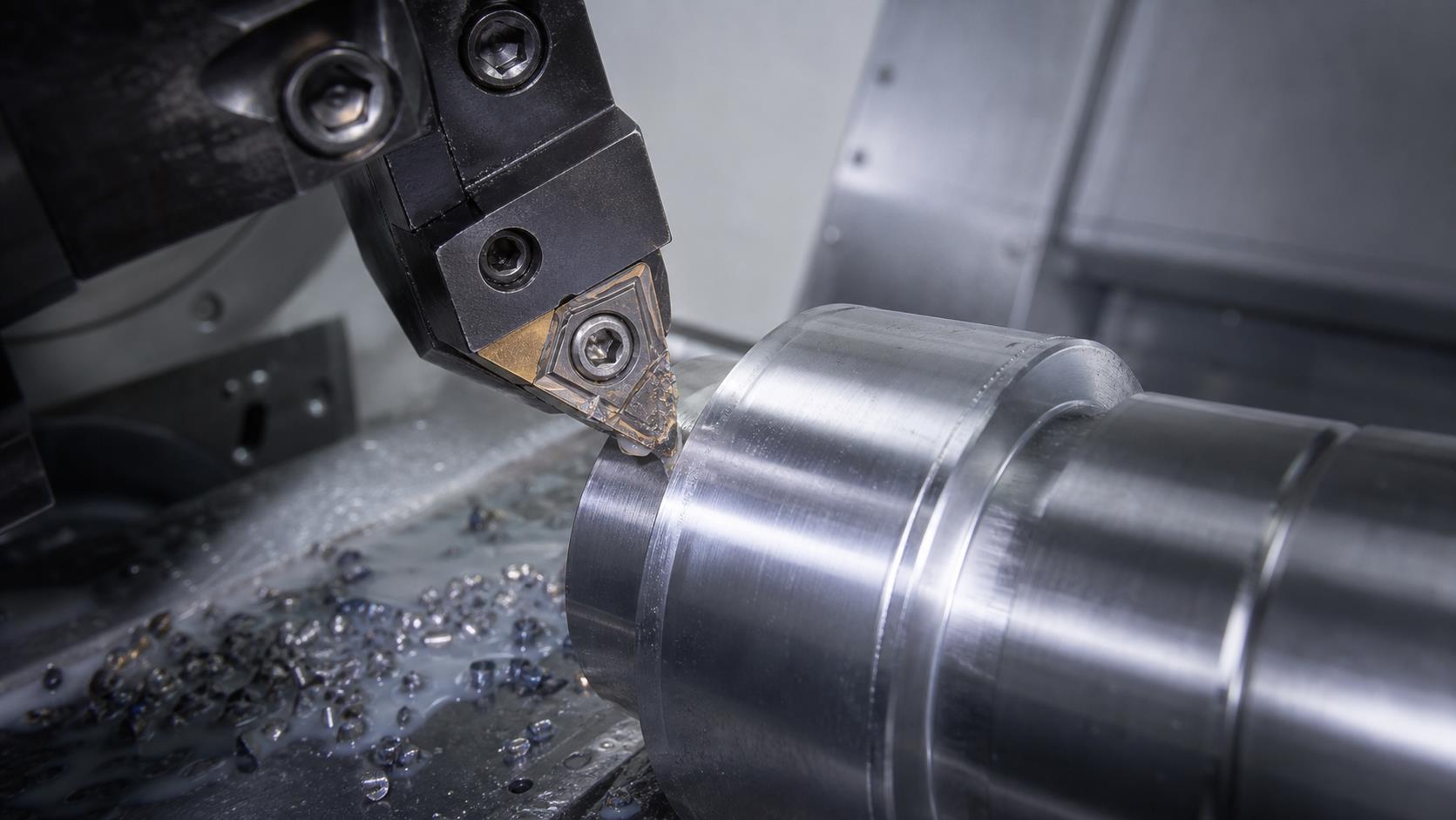
Cutting tools are consumable components in every CNC machining center. Wear is unavoidable, but premature edge chipping, cracking, deformation and fracture often point to incorrect tool selection, unstable machining, unsuitable cutting parameters or poor maintenance.
Recognizing each failure pattern helps manufacturers protect part quality, extend tool life and reduce unplanned downtime. This guide connects common symptoms with likely causes and practical corrective actions.
1. Common Types of Cutting Tool Failure
Micro Edge Chipping
Small fragments break away because of uneven hardness, interrupted cuts, weak edge geometry, grinding defects or poor rigidity. Continued use can lead to severe breakage.
Edge or Tip Breakage
Excessive loads, unstable engagement or continued use after initial chipping can destroy the edge.
Tool Fracture
Complete fracture may result from impact loading, extreme force, material defects, grinding cracks or operator error.
Coating Delamination
Residual stress, coating defects, thermal cycling and unstable cutting can cause surface layers to peel.
Plastic Deformation
High temperature and heavy load permanently change cutting-edge geometry and reduce accuracy.
Thermal Cracking
Repeated heating and cooling in interrupted or high-speed milling creates fatigue cracks.
2. Main Causes of Tool Wear
Abrasive Wear
Hard particles scratch the tool surface. This occurs at almost all speeds and worsens when tool hardness is insufficient.
Adhesive (Cold-Welding) Wear
High pressure welds chip material microscopically to the tool. Moving chips then tear particles from the edge, especially at medium speed.
Diffusion Wear
At elevated temperature, atoms migrate between tool and workpiece, changing the edge composition. It becomes increasingly important above approximately 800°C.
Oxidation Wear
High temperature forms softer oxides that are easily removed, accelerating wear.
3. Common Tool Wear Patterns
| Pattern | Location | Effect |
|---|---|---|
| Crater wear | Rake face | Weakens the cutting edge |
| Nose wear | Nose radius and adjacent flank | Reduces dimensional, profile and finish accuracy |
| Flank wear | Flank face at the machined surface | Raises force and vibration; measured as VB |
4. How to Prevent Premature Tool Failure
Select tool material with the right balance of hardness, wear resistance and toughness.
Optimize rake, clearance, lead and inclination angles; use edge preparation where appropriate.
Improve grinding quality to minimize residual stress and micro-cracks.
Avoid excessive cutting speed, feed, depth of cut and temperature.
Improve fixture and holder rigidity and minimize tool overhang.
Use smooth entry strategies and avoid sudden impact loads.
5. Edge Chipping: Causes and Solutions
Frequent Causes
Incorrect grade, weak geometry, grinding defects, aggressive parameters, weak holders, worn inserts, poor coolant delivery, incorrect installation and low machine rigidity.
Corrective Actions
Use tougher or thicker inserts, strengthen edge geometry, reduce unstable loads, replace worn edges, improve coolant flow, shorten overhang and reinforce fixturing.
6. Built-Up Edge (BUE): Causes and Prevention
BUE forms when workpiece material adheres to the cutting edge under high pressure. It usually causes unstable cutting, dimensional errors, tearing and poor finish.
Polish the rake face and increase rake angle appropriately.
Reduce chip thickness and select a speed outside the BUE range.
Where practical, increase workpiece hardness through heat treatment.
Use cutting fluid with strong anti-adhesion performance.
7. Quick Tool-Wear Diagnosis
| Symptom | Check first | Response |
|---|---|---|
| Micro-chipping | Rigidity, edge strength, engagement | Use a tougher grade and stabilize entry |
| Rapid flank wear | Speed, material abrasiveness, tool hardness | Lower speed or use a wear-resistant grade |
| Thermal cracks | Temperature cycling and coolant | Stabilize thermal conditions |
| Plastic deformation | Heat, load and hot hardness | Reduce load or change tool grade |
| Built-up edge | Speed, rake-face finish and lubrication | Optimize speed and lubrication |
Frequently Asked Questions
What is the most common tool wear pattern?
Flank wear is the most common and its wear-land width, VB, is widely used as a tool-life criterion.
Why do CNC tools chip prematurely?
Common causes include weak edge geometry, low rigidity, interrupted cutting, an unsuitable grade, aggressive parameters and grinding defects.
Can tool wear be eliminated?
No, but correct tooling, parameters, coolant, rigidity and inspection can greatly reduce premature failure.
Conclusion
Tool wear is natural, but early failure is often preventable. Identifying abrasive, adhesive, diffusion, oxidation and thermal damage supports better decisions about tool grades, geometry, cutting data, coolant and setup.
Stable fixturing, short overhang, suitable parameters, effective lubrication and routine inspection improve tool life, surface quality and production reliability.