
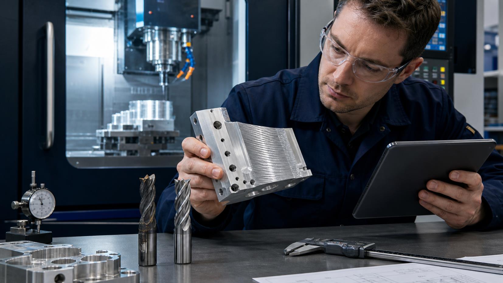
Even with advanced CNC equipment and high-quality cutting tools, machining problems can still occur during production. Overcutting, setup errors, poor surface finish, rapid wear, tool breakage, machine collisions, and chatter can reduce accuracy, increase costs, and shorten tool life.
This practical CNC machining troubleshooting guide summarizes ten common problems, their likely causes, and corrective actions. It also explains how cutting speed, feed, and depth of cut should work together for stable and efficient machining.
1. Overcutting
Possible Causes
Long or undersized tools causing excessive deflection
Incorrect setup or operator error
Uneven allowance between walls and floors
Aggressive parameters or unsuitable tolerance settings
Recommended Solutions
Use the largest and shortest tool the geometry allows
Maintain consistent side and bottom allowance
Smooth sharp toolpath transitions
Optimize parameters and adjust feed override cautiously
2. Incorrect Workpiece Centering
Possible Causes
Inaccurate manual centering
Burrs or contamination on reference edges
Magnetized edge finder or centering tool
Workpiece or mold surfaces not square
Recommended Solutions
Repeat measurements from the same reference
Deburr and clean all locating surfaces
Demagnetize the centering tool if required
Verify squareness using a dial indicator
Foundation of accuracy: Reliable workpiece positioning must be established before tool offsets and programs can produce accurate results.
3. Tool-Setting Errors
Possible Causes
Incorrect manual tool measurement
Improper tool clamping or seating
Face-mill insert positioning differences
Different reference behavior between cutter types
Recommended Solutions
Double-check all tool-length offsets
Clean holder and spindle taper before installation
Measure individual inserts when necessary
Use verified tool-setting routines for different cutters
4. Machine Collision Caused by Programming Errors
Common Causes
Insufficient safety clearance
Incorrect tool number or length
Wrong Z-axis reference value
Coordinate-system errors
Recommended Solutions
Measure workpiece and fixture height accurately
Match setup sheets to the released program
Verify tool length, reach, and cutting depth
Simulate and perform controlled dry runs
5. Machine Collision Caused by Operation Errors
Common Causes
Incorrect Z-axis tool setting
Wrong workpiece zero point
Wrong cutting tool or NC program
Incorrect manual movement direction
Recommended Solutions
Verify tool and work offsets carefully
Confirm tool numbers before installation
Run programs in the approved sequence
Retract Z to a safe position before jogging
Standardized setup checks, clear program identification, single-block verification, and disciplined operating habits greatly reduce collision risk.
6. Poor Surface Finish
Possible Causes
Unsuitable speed, feed, or tolerance
Worn cutting edges
Excessive tool overhang
Poor chip evacuation or unsuitable toolpath
Burr formation
Recommended Solutions
Optimize spindle speed, feed, stepover, and allowance
Replace worn tools before quality deteriorates
Minimize tool overhang
Improve chip removal using coolant or air
Use climb milling when suitable
7. Cutting-Edge Chipping
Possible Causes
Feed rate or chip load too high
Loose tool or workpiece clamping
Insufficient machine or setup rigidity
Cutting geometry too sharp for the load
Recommended Solutions
Reduce feed or engagement
Improve tool and workpiece clamping
Use shorter tools and more rigid holders
Select a stronger edge preparation or geometry
8. Excessive Tool Wear
Possible Causes
Excessive spindle or cutting speed
Hardened or abrasive material
Chip adhesion and built-up edge
Feed too low, causing rubbing
Unsuitable tool material or geometry
Recommended Solutions
Reduce cutting speed where necessary
Use suitable substrate and coating
Improve chip evacuation and coolant delivery
Increase feed appropriately to form a stable chip
Match tool geometry to the material
9. Tool Breakage
Possible Causes
Excessive feed rate
Excessive axial or radial depth
Long cutting-edge engagement
Severe accumulated tool wear
Recommended Solutions
Reduce chip load and cutting engagement
Decrease depth of cut
Use the shortest practical cutting tool
Replace worn tools before catastrophic failure
10. Chatter and Vibration Marks
Possible Causes
Unstable spindle speed or feed combination
Insufficient machine, holder, or tool rigidity
Unsuitable cutting-edge geometry
Loose or flexible workpiece fixturing
Recommended Solutions
Change spindle speed and optimize feed
Use more rigid holders and shorter overhang
Select suitable cutting geometry and pitch
Improve workpiece support and clamping
Optimizing Cutting Parameters
Cutting speed, feed per tooth, and depth of cut interact. A stable process requires a suitable combination for the workpiece material, cutting-tool geometry, machine rigidity, engagement, and required surface quality.
Cutting speed strongly affects heat generation and tool life.
Feed per tooth determines chip thickness and cutting load.
Axial and radial engagement determine force and material removal.
Use Lower Cutting Speeds For
Hard or difficult-to-machine alloys
Heavy roughing operations
Reducing cutting temperature
Extending tool life
Use Higher Cutting Speeds For
Softer, free-machining materials
Light finishing cuts
Smaller tool diameters where appropriate
Higher productivity within tool limits
Use Higher Feed Rates For
Roughing with rigid setups
Coarse-pitch cutters
Lower-strength materials
High material-removal operations
Use Lower Feed Rates For
Finishing and fine surface requirements
Small-diameter tools
Deep slots with limited chip evacuation
Brittle or high-strength materials
Important: Feed should not be reduced so far that the cutting edge rubs instead of forming a chip. Always remain within the tool manufacturer's recommended operating range.
CNC Troubleshooting Checklist
Confirm the correct program, revision, tool list, and setup sheet.
Verify work offsets, tool offsets, coordinate systems, and safe clearances.
Inspect spindle taper, holder, tool, fixture, and workpiece cleanliness.
Check tool wear, runout, overhang, clamping, and insert seating.
Confirm material, hardness, allowance, and workpiece positioning.
Review speed, feed, axial depth, radial engagement, and coolant.
Observe chip shape, sound, vibration, spindle load, and surface marks.
Change one variable at a time and record the result.
Frequently Asked Questions
What should be checked first when a CNC machining problem occurs?
Confirm the correct program, setup, tool, offsets, material, and workholding. Then inspect tool condition and review cutting parameters before making process changes.
Why does a low feed rate sometimes increase tool wear?
If chip thickness becomes too small, the cutting edge may rub or plough instead of cutting cleanly. This increases friction, heat, and wear.
How can CNC collisions be prevented?
Use verified setup sheets, accurate tool and work offsets, simulation, clearance checks, controlled dry runs, single-block execution, and disciplined program identification.
What is the fastest way to reduce chatter?
Shorten tool overhang, improve clamping, and make a meaningful spindle-speed change. Then optimize feed and engagement while monitoring surface finish and tool load.
Should several machining parameters be changed at once?
Usually not. Change one controlled variable at a time so the actual cause and effect can be identified and documented.
Conclusion
Successful CNC machining requires more than selecting a suitable cutting tool. Reliable production depends on correct positioning, clean and rigid setups, verified programs and offsets, appropriate tooling, controlled cutting parameters, effective chip evacuation, and disciplined operating practices.
By identifying root causes and applying targeted corrective actions, manufacturers can reduce defects, improve surface finish and accuracy, extend tool life, and achieve more stable CNC production.