
To improve CNC machine utilization and minimize machine downtime, maintenance personnel need a systematic method for identifying, diagnosing and repairing faults. A practical CNC troubleshooting framework can be summarized as four steps: Observe, Smell and Listen, Ask, and Diagnose.
These methods combine direct inspection, operator evidence, CNC alarm diagnosis, electrical measurement, operating-principle analysis and controlled component substitution. Used together, they help maintenance teams avoid blind part replacement and restore reliable manufacturing more efficiently.
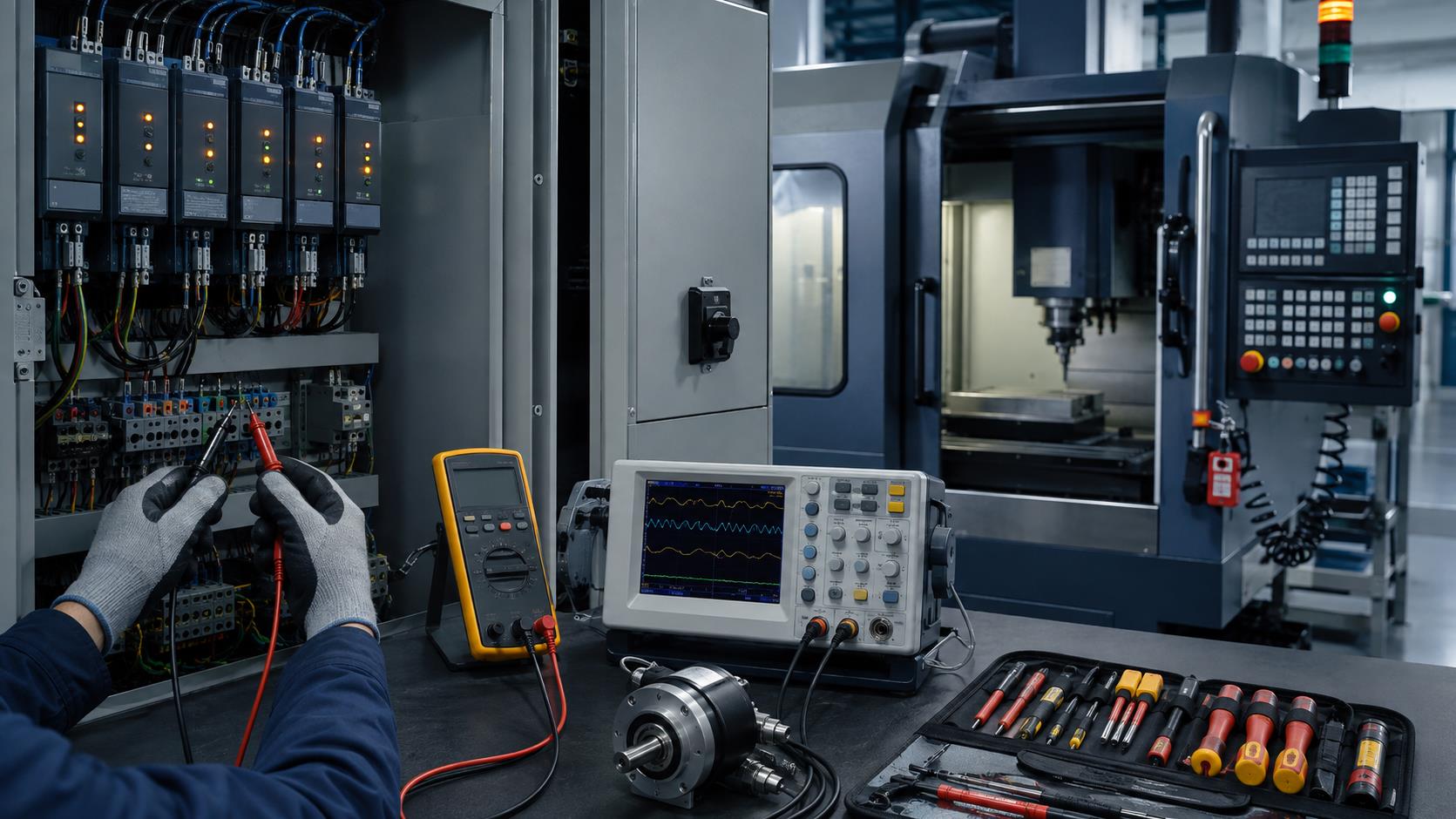
1. A Practical CNC Troubleshooting Workflow
Observe
Inspect visible, physical and operational signs. Reproduce the fault only when it can be done safely.
Smell and Listen
Identify unusual odors, friction sounds, electrical discharge or abnormal mechanical noise.
Ask
Collect detailed information from the operator and preserve fault conditions, alarms and defective parts.
Diagnose
Use system data, measurements, control principles and verified substitution to isolate the root cause.
2. Observe: Inspect Visible and Physical Signs
Begin CNC fault diagnosis by determining what happened, when it occurred, what immediately preceded it and whether it can be reproduced safely. Watch the complete sequence rather than only the final alarm.
Mechanical Signs
Damage, looseness or jammed motion
Oil leakage or detached material
Abnormal moving or sealed components
Incorrect switch or mechanism position
Electrical Signs
Burn marks or discolored wiring
Tripped breakers, relays or blown fuses
Loose connectors or broken conductors
Missing phase, imbalance or abnormal voltage
Control and Process Signs
CNC, PLC or drive alarms
Unexpected machine behavior
Operator-program errors
Fault linked to one tool, program or part
3. Smell and Listen: Identify Abnormal Odors and Sounds
Mechanical Friction
Severe rubbing may create heat, oil vapor, smoke or a change in bearing, gearbox, spindle or axis sound.
Electrical Overheating
Burning insulation can create a distinctive odor. Electrical discharge may produce an ozone-like smell and audible crackling.
4. Ask: Collect Detailed CNC Fault Information
Operators often hold the only first-hand evidence. Stop the machine, preserve the fault state where safe and document the event before resetting or altering conditions.
| Information to record | Why it matters |
|---|---|
| Exact symptom and location | Defines the affected machine function and narrows the search area |
| Operating mode and machine state | Separates manual, automatic, startup and thermal-condition faults |
| Alarm message and CNC alarm code | Links symptoms to CNC, PLC, servo and drive diagnostics |
| Repeatability and frequency | Distinguishes persistent, intermittent and part-dependent problems |
| Program number and block | Connects the event to a command, position or machining sequence |
| Tool number and cutting conditions | Identifies tooling, load and process-related causes |
| Part number and defective component | Supports dimensional, contour and process analysis |
| Events immediately before failure | Reveals maintenance, collision, power, setup or parameter changes |
5. Diagnose: Identify the Root Cause
Diagnosis turns symptoms into a verified cause. Start with the least invasive evidence, confirm each assumption and avoid creating a second fault while testing the first.
System Information
Read CNC alarms, PLC status, drive indicators, diagnostic bits and parameter records.
Objective Measurement
Measure voltage, phase sequence, signal waveform, continuity and mechanical conditions with suitable instruments.
Functional Isolation
Analyze operating logic and substitute known-good components only after compatibility and safety are confirmed.
6. Check CNC System Parameters and Alarm Information
Modern CNC systems provide alarms and diagnostics from the CNC unit, PLC, servo amplifiers and drives. Consult the correct machine maintenance manual and control documentation before changing parameters.
Alarm Investigation
Record every displayed code and message
Check related PLC and drive alarms
Review axis position and interlock status
Compare parameters with a controlled backup
Stored-Stroke Example
In the source case, FANUC alarms 500 and 501 indicated positive or negative stored-stroke limits. Manual recovery returned the turret to its permitted range before parameters were corrected and alarms cleared.
7. Reset, Power Cycling and CNC Initialization
Some alarms are transient and may clear through an approved hardware reset or correct power-off and restart sequence. A reset is a diagnostic step, not proof that the underlying fault has been removed.
When Reset May Help
Temporary communication or sequence fault
Recoverable control-state error
Condition already corrected by the operator or technician
When Data Is at Risk
Power loss, circuit-board removal or low battery voltage may corrupt working memory. Back up parameters, offsets, programs and other essential data before initialization or memory clearing.
8. Measurement-Based CNC Diagnostics
| Instrument | Typical diagnostic use | Important consideration |
|---|---|---|
| Multimeter | Voltage, resistance, continuity and selected current checks | Use the correct category, range and safe electrical procedure |
| Oscilloscope | Encoder, command, feedback and power waveform analysis | Correct grounding and probe selection are essential |
| Logic tester | Digital input, output and control signal checking | Compare against circuit and PLC documentation |
| Phase-sequence meter | Three-phase supply sequence | Correct sequence and phase condition are required for intended operation |
| Mechanical indicators | Runout, backlash, alignment and lost motion | Separate mechanical error from control or feedback error |
For a correct three-phase relationship, phase pairs have the expected 120-degree separation. Measurements should confirm a hypothesis rather than merely collect unrelated data.
9. Analyze the CNC Machine Operating Principle
When ordinary checks do not identify the cause, trace the machine function step by step: command, PLC condition, drive output, motor motion, mechanical transmission and feedback signal.
Threading Fault Example
A FANUC 0i-TD lathe produced incorrect or crossed threads. Because spindle-position feedback is essential for thread interpolation, the rotary encoder became a primary suspect.
Verified Root Cause
Inspection found a broken internal encoder filament and loss of feedback input. Replacing the encoder restored correct CNC threading.
10. Use Component Substitution Carefully
A suspected component may be compared with an identical, compatible and known-good spare when direct testing is difficult. If the fault disappears, the original part becomes a strong suspect. If the symptom remains, continue diagnosis elsewhere.
Confirm exact compatibility, configuration and firmware requirements.
Back up data and document connectors, parameters and orientation.
Isolate energy and use approved electrostatic and electrical precautions.
Change only one controlled variable at a time.
Verify the machine safely before returning it to production.
11. Preventive CNC Machine Maintenance
The same evidence used in CNC troubleshooting should improve preventive maintenance. Record recurring alarms, component temperatures, lubrication, battery condition, electrical-cabinet cleanliness, coolant contamination and axis behavior before they become production failures.
Daily and Shift Checks
Leaks, lubrication and coolant condition
Abnormal sound, smell or vibration
Guards, interlocks and emergency controls
Air pressure and chip removal
Scheduled Checks
Filters, fans and cabinet temperature
Electrical terminals and grounding
Backup batteries and verified data backups
Backlash, runout and alignment trends
Reliability Records
Alarm history and downtime duration
Replaced components and root causes
Repeat faults by program, tool or part
Corrective action and verification results
12. CNC Fault Diagnosis Quick Reference
| Symptom | Initial evidence | Possible next check |
|---|---|---|
| Axis will not move | Limit, interlock, servo and PLC alarms | Axis position, stored-stroke status, enable chain and drive condition |
| Intermittent shutdown | Alarm history, cabinet heat, power events | Cooling fans, supply quality, loose connections and thermal trends |
| Position or contour error | Defective part, offsets, feedback and load | Encoder signals, backlash, coupling, servo data and program |
| Crossed CNC threads | Spindle synchronization and repeatability | Encoder, feedback wiring and threading parameters |
| Burning odor or smoke | Location and operating state | Immediate safe isolation, then qualified inspection for overheating or damage |
CNC Machine Maintenance FAQ
What is the first step in CNC troubleshooting?
Preserve the fault condition where safe, record what happened and inspect visible, audible and physical signs before changing parameters or replacing components.
Should every CNC alarm be cleared by resetting the machine?
No. Record the alarm and investigate its cause first. A reset may clear a transient state but can also remove useful evidence or allow a real fault to recur.
Why are operator fault records important?
They connect symptoms to the program block, tool, workpiece, mode, alarm and operating condition present at the moment of failure.
When should component substitution be used?
Use it when a component is difficult to test directly and an identical, compatible known-good unit can be exchanged safely under a controlled procedure.
How does preventive maintenance reduce machine downtime?
Regular inspection and trend records reveal lubrication, cooling, electrical, battery, backlash and component problems before they interrupt production.
Need Reliable CNC Machining and Process Support?
Zentoc provides precision CNC machining and custom manufacturing supported by controlled equipment maintenance, process verification and quality management.
Contact Zentoc