
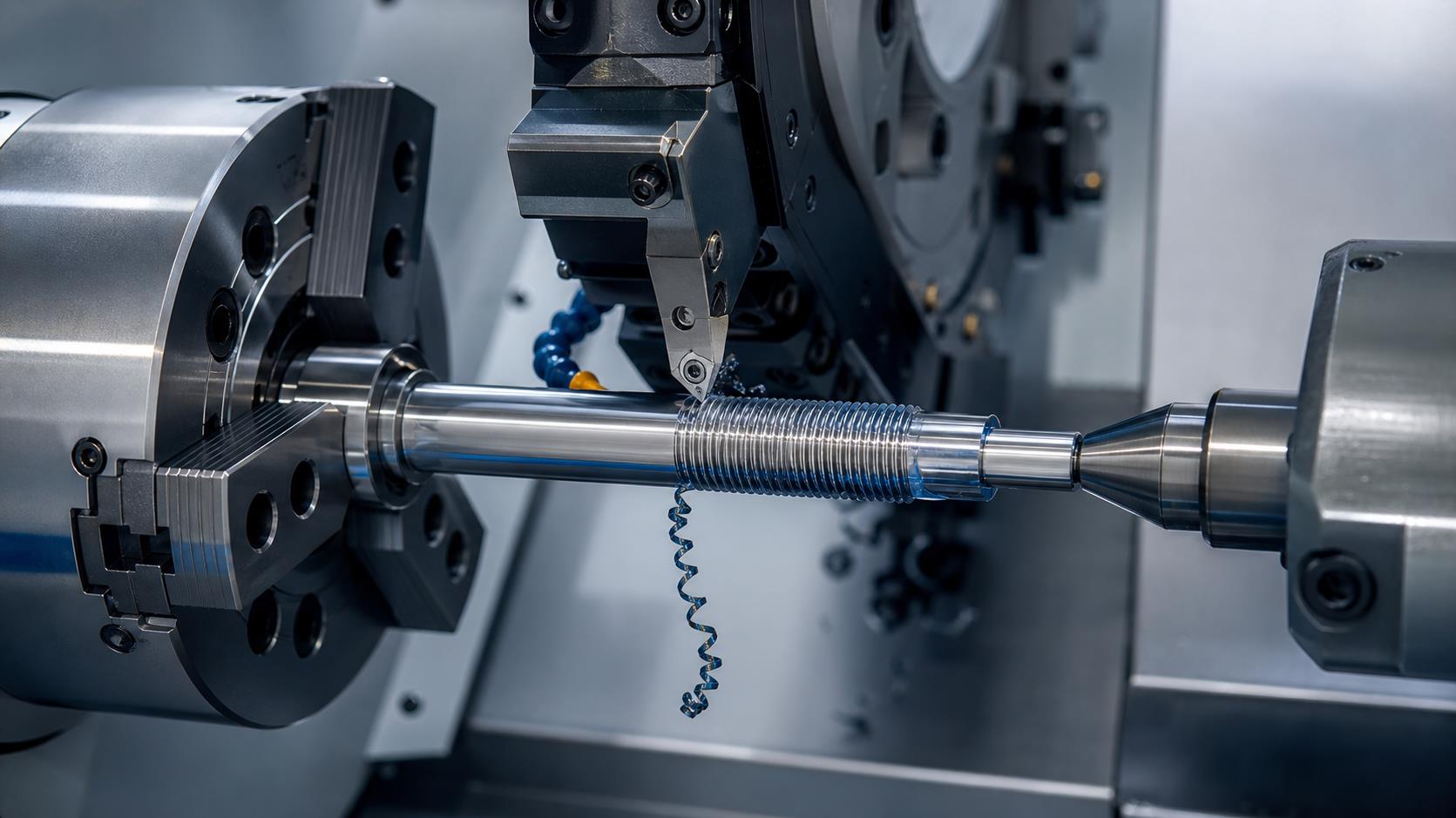
CNC lathe threading is a common but precision-sensitive CNC turning operation. Metric, inch, module and diametral-pitch threads all depend on strict synchronization: for every complete spindle revolution, the threading tool must travel exactly one thread lead in the axial direction.
Reliable CNC thread cutting requires correct thread dimensions, tool-center height, workholding rigidity, threading-cycle selection, progressive infeed, tool-wear control and final thread inspection.
1. Standard Thread Dimensions for CNC Lathe Threading
Before programming a CNC threading cycle, determine the starting diameter, pitch, lead, thread height, minor diameter and radial infeed. The exact standard and tolerance class must come from the drawing or applicable specification.
Starting Workpiece Diameter
Starting diameter = major diameter - 0.1P
Here, P is thread pitch. Depending on material deformation, the practical starting diameter may be about 0.1 to 0.5 mm below the nominal major diameter.
Approximate Thread Depth
Thread height = 0.54PMinor diameter = major diameter - 2 x thread height
These relationships reflect the original process example and must be verified against the actual thread standard and profile.
2. CNC Threading Tool Installation and Center Height
Tool Too High
With increasing depth, the flank face may rub the workpiece. Friction and radial force can deflect the part and cause abnormal digging.
Tool Too Low
Chip evacuation becomes difficult. Cross-slide backlash and inward cutting force may create an unintended increase in effective depth.
Correct Position
Align the cutting tip approximately with the spindle centerline, using the tailstock center or a qualified setting device as reference.
3. Secure the Workpiece Before Thread Cutting
Insufficient rigidity allows the part to deflect under radial cutting force. Deflection changes the relative center height and can suddenly increase tool engagement, damage the thread or break the insert.
Chuck and Grip
Use adequate jaw contact and clamping force without distorting thin-walled parts. Minimize unsupported length where possible.
Additional Support
For long or flexible shafts, use a tailstock center, steady rest or suitable process-specific support to improve rigidity.
4. CNC Lathe Threading Tool-Setting Methods
Common Methods
-
Trial-cut tool setting
-
Automatic tool setter
-
Workpiece zero established with G50 where applicable
-
Work-coordinate offset method
Critical Requirement
Establish a reliable X and Z reference so every threading pass begins with the correct diameter, axial start position and synchronization.
5. CNC Thread Programming: G32 vs. G92 vs. G76
| Method | Cutting strategy | Advantages | Limitations and best use |
|---|---|---|---|
| G32 threading | Direct programmed thread motion, commonly straight infeed | High programming control and potentially strong profile accuracy | Longer program, both edges cut, higher force and difficult chip control; suited to smaller-pitch or precision finishing applications |
| G92 threading cycle | Repeated straight-in threading cycle | Simplifies programming and improves efficiency compared with programming every G32 movement | Both edges share the cut; use for conventional straightforward thread cutting |
| G76 threading cycle | Multi-pass cycle with oblique or flank infeed | Lower load, easier chip evacuation and automatic progressive depth reduction | One edge carries more load and profile accuracy can be affected by localized wear; useful for larger-pitch threads |
6. Combining G76 and G32 for Higher-Precision Threads
Rough with G76
Remove most thread material efficiently with manageable tool load, progressive infeed and improved chip evacuation.
Finish with G32
Use controlled finishing passes to refine the profile and pitch diameter.
7. Evaluate Thread Quality During CNC Machining
Inspect the developing thread profile before removing more material. When the crest is not yet sharp, additional infeed may cause material deformation that increases the measured major diameter. After the crest becomes sharp, further infeed may reduce major diameter.
Check the Crest
Observe whether the crest is still flat, approaching shape or already sharp.
Measure Progress
Use the appropriate pitch-diameter or functional inspection method rather than relying only on programmed depth.
Monitor the Insert
Flank wear, chipping and built-up edge can change profile angle, pitch diameter and surface finish.
8. Standard Thread Inspection After CNC Turning
External Threads
Use GO and NO-GO thread ring gauges where specified. The GO gauge should assemble as required, while the NO-GO gauge must not exceed the permitted engagement condition.
Internal Threads
Use GO and NO-GO thread plug gauges. The GO member verifies functional size and the NO-GO member checks the limiting condition.
9. Other Thread Measurement Methods
| Method | What it checks | Application note |
|---|---|---|
| Thread micrometer | Thread pitch diameter | Uses matched anvils for the selected pitch range |
| Three-wire method | Measurement over wires related to pitch diameter | Uses precision wires and the applicable calculation or reference value |
| Gear-tooth vernier caliper | Selected chordal or tooth-thickness characteristics | Can support trapezoidal or worm-thread measurements according to the defined method |
| Optical or profile inspection | Flank angle, pitch, crest, root and profile form | Useful when geometry needs more detail than functional gauging alone |
10. Practical CNC Lathe Threading Tips
-
Maintain synchronization: move exactly one thread lead for every spindle revolution.
-
Prepare the starting diameter: account for pitch, tolerance and material deformation.
-
Set the insert on center: incorrect height can cause rubbing, poor chip control and digging.
-
Increase workpiece rigidity: support long or flexible parts.
-
Reduce infeed progressively: avoid excessive constant depth throughout the cycle.
-
Select the right cycle: match G32, G92 or G76 to pitch, accuracy, chip control and controller capability.
-
Monitor tool wear: insert condition directly affects pitch diameter and profile accuracy.
-
Control the start position: especially when combining roughing and finishing strategies.
-
Inspect before cutting deeper: use profile condition and measurements to decide the next correction.
-
Use appropriate inspection tools: select gauges, micrometers, wires or optical measurement according to requirements.
CNC Lathe Threading FAQ
What is the most important synchronization rule in CNC threading?
For every full workpiece revolution, the tool must move one thread lead in the axial direction. For a single-start thread, lead equals pitch.
When is G76 useful for CNC thread cutting?
G76 is useful for efficient multi-pass threading, particularly larger-pitch threads where flank infeed can reduce cutting load and improve chip evacuation.
Why combine G76 roughing with G32 finishing?
The combination uses G76 for efficient stock removal and G32 for controlled finishing, provided the finishing tool enters the existing groove accurately.
Why does threading tool height matter?
Incorrect center height changes clearance and cutting geometry, which can increase friction, restrict chips, deflect the part and produce abnormal infeed.
How are external CNC threads commonly inspected?
Functional acceptance often uses calibrated GO and NO-GO ring gauges. Pitch diameter can also be checked with a thread micrometer or three-wire measurement.
Need Precision CNC Turned and Threaded Components?
Zentoc provides CNC turning, thread machining and custom manufacturing support for precision shafts, fittings, fasteners and other metal components.
Contact Zentoc