
After prolonged use, a three-jaw lathe chuck gradually loses clamping accuracy as the jaws and chuck-body guideways wear. Reduced concentricity and bellmouth-shaped jaw surfaces can increase workpiece runout, weaken clamping reliability and lower machining precision.
In many cases, the chuck does not need immediate replacement. Careful re-machining or grinding of the hard jaws with correctly prepared reference components can restore jaw geometry, improve repeatability and extend chuck service life.
1. Why Does Bellmouth Wear Occur?
Repeated clamping gradually increases clearance between the jaws and their guide slots. Under load, the jaws no longer remain perfectly parallel to the spindle axis. The gripping diameter becomes slightly larger near the jaw front, creating the tapered condition commonly called bellmouth wear.
2. Typical Symptoms of a Worn Three-Jaw Chuck
Accuracy Problems
Reduced concentricity, higher radial runout and inconsistent workpiece positioning.
Clamping Problems
Uneven contact, unstable holding force and reduced repeatability between parts.
Part Quality Problems
Lower dimensional accuracy, poor finishes and surface marking during clamping.
3. Simple Method to Correct Chuck Bellmouth Wear
The following procedure uses a standard forward hard-jaw chuck as an example. The machine must be isolated during setup, and the reference parts, chuck key and tools must be removed or secured before rotation.
Machine the Outside of the Chuck Jaws
Clamp a precision round bar with the external gripping surfaces of the jaws. While the bar maintains the jaws under a controlled load, lightly machine the outside jaw surfaces to establish an accurate reference for the next setup.
Install a Precision Reference Ring
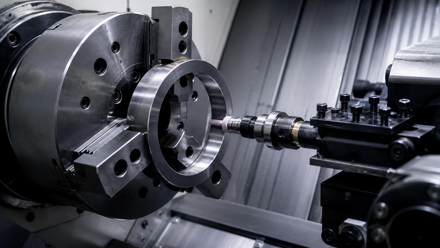
Place a precision-machined ring against the internal gripping surfaces. Expand the jaws securely into the ring so they are loaded in a controlled direction during correction.
Machine the Inner Gripping Surfaces
Lightly machine or grind the internal jaw gripping surfaces and the required jaw faces. This restores their relationship to the spindle centerline and removes much of the bellmouth error.
Clean and Verify
Remove all abrasive particles and chips, reinstall the chuck components as required, then test a precision bar at multiple clamping positions with a dial indicator.
4. Precision Reference Components Matter
Precision Round Bar
The bar used during the first operation must have suitable roundness, straightness and diameter accuracy because it establishes the machining reference.
Expansion Ring
The ring must be accurately machined, rigid and sized for the intended future clamping range. Its geometry directly affects corrected jaw contact.
Select an Appropriate Ring Diameter
An excessively small ring can create an overly deep concave jaw profile. When a larger workpiece is clamped later, concentrated contact near the jaw front may mark the part and reduce clamping stability. Select a ring diameter representative of the workpiece sizes the chuck will normally hold.
5. Compensating for Jaw and Guideway Clearance
Clearance always exists between the jaws and the chuck-body guideways. Cutting force during jaw correction may act in the opposite direction from normal workpiece clamping force. If the jaws are machined perfectly cylindrical under the wrong load condition, bellmouth error may return when the chuck is used.
6. Recommended Cutting and Grinding Practice
Hard jaws are made from hardened steel, and jaw correction is an interrupted operation. The cutting edge experiences repeated impact, so conservative parameters and a rigid setup are essential.
| Factor | Recommendation | Reason |
|---|---|---|
| Depth of cut | Use shallow passes | Limits impact loading and jaw deflection |
| Feed rate | Use a light, stable feed | Improves finish and reduces tool stress |
| Cutting speed | Avoid excessive speed | Controls heat and interrupted-cut shock |
| Tooling | Use a suitable high-quality carbide tool | Provides hardness and edge strength |
| Finishing | Consider an internal grinding attachment | Can improve surface finish and geometric accuracy |
Why the Outside-Jaw Operation Matters
The initial outside-surface operation is often skipped, but it creates a more stable reference condition for the final correction. A small amount of preparation can produce a meaningful improvement in final chuck concentricity.
7. Applications Beyond Heavily Worn Chucks
The same controlled jaw-correction principle can help address several other conditions:
New chucks affected by mounting or installation error
Assembly inaccuracies after maintenance
Poor initial concentricity
Chuck alignment problems
Reverse-jaw correction for larger workpieces
Before machining any jaw, confirm that the root cause is actually jaw geometry. Spindle runout, chuck mounting error, trapped chips, damaged scrolls and excessive guide wear may require different corrective actions.
Frequently Asked Questions
Can every worn three-jaw chuck be repaired by machining the jaws?
No. If the scroll, jaw guides, chuck body or mounting interface is severely damaged, jaw correction alone may not restore safe and reliable performance.
Why must the jaws be loaded during machining?
Loading places the jaws in a repeatable position within their guideway clearance, helping the corrected surface better represent the condition used during actual clamping.
Is cutting or grinding better for hard-jaw correction?
Carbide cutting can be practical for correction, while finish grinding often provides better surface finish and geometric control. The best method depends on equipment, jaw hardness and accuracy requirements.
How should the expansion-ring diameter be selected?
Choose a diameter representative of the normal workpiece range. A ring that is too small can produce an unsuitable jaw profile for larger parts.
How is the repair result verified?
Clamp a certified or accurately ground test bar, measure runout with a dial indicator, repeat the test at several clamping positions and confirm stable jaw contact.
Conclusion
Three-jaw chuck bellmouth wear is a common cause of reduced accuracy in CNC and manual turning. Instead of immediately replacing an expensive chuck, shops can often restore useful performance by correcting the hard jaws with accurately prepared reference components and controlled machining or grinding.
Successful results depend on understanding guideway clearance, selecting a suitable ring diameter, using conservative cutting conditions and verifying the chuck afterward. Regular inspection and timely correction help improve concentricity, reduce scrap and maintain reliable production.
Chuck repair involves rotating machinery and hardened components. Work should be performed by qualified personnel using the chuck and machine manufacturers' safety requirements. Replace the chuck when structural damage or unsafe wear is present.